Ashcroft T2 - High Performance Pressure Transmitter User Manual
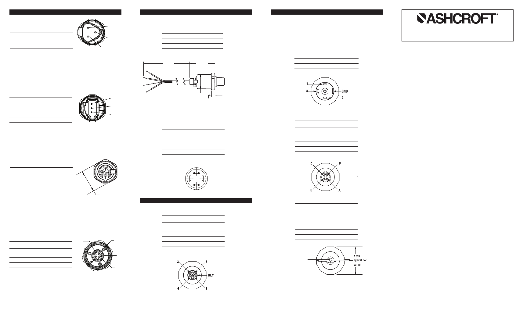
3 (a) 2 (c) 1 (b), T2 electrical terminations and wiring
G2 & T2 PRESSURE TRANSMITTER
INSTRUCTION SHEET
WARNING! READ
BEFORE INSTALLATION
1. GENERAL:
A failure resulting in
injury or damage may be
caused by excessive overpressure, excessive vi-
bration or pressure pulsation, excessive instrument
temperature, corrosion of the pressure containing
parts, or other misuse. Consult Ashcroft Inc., Strat-
ford, Connecticut, USA before installing if there are
any questions or concerns.
2. OVERPRESSURE:
Pressure spikes in excess of the rated overpressure
capability of the transducer may cause
irreversible
electrical and/or mechanical damage to the pres-
sure measuring and containing elements.
Fluid hammer and surges can destroy any pressure
transducer and must always be avoided. A pressure
snubber should be installed to eliminate the damag-
ing hammer effects. Fluid hammer occurs when a liq-
uid flow is suddenly stopped, as with quick closing
solenoid valves. Surges occur when flow is suddenly
begun, as when a pump is turned on at full power or
a valve is quickly opened.
Liquid surges are particularly damaging to pressure
transducers if the pipe is originally empty. To avoid
damaging surges, fluid lines should remain full (if
possible), pumps should be brought up to power
slowly, and valves opened slowly. To avoid damage
from both fluid hammer and surges, a surge cham-
ber should be installed.
Symptoms of fluid hammer and surge's damaging
effects:
• Pressure transducer exhibits an output at zero
pressure (large zero offset).
• Pressure transducer output remains constant re-
gardless of pressure
• In severe cases, there will be no output.
FREEZING:
Prohibit freezing of media in pressure port. Unit
should be drained (mount in vertical position with
electrical termination upward) to prevent possible
overpressure damage from frozen media.
ƽ
ƽ
M12 ELECTRICAL TERMINATION
FOR T2 (EW), (EO), (E2), (E1)
Mates to optional Hirschmann connector
Part 933 172-100 or equal
Pin
Voltage
4-20mA
Mating
No.
Output
Output*
Cable Color
1
V +
V +
Red
2
Output
None
White
3
Case Gnd.
Case Gnd.
Green
4
Common
Common
Black
IP65 Ingress rating
DIN 43650 FORM A (EN 175301-803-A)
ELECTRICAL TERMINATION
(DN), (DO), (D2), (D1)
Mates to optional Hirschmann connector
GDM 3009 or equal
Pin
Voltage
4-20mA
Mating
No.
Output
Output*
Cable Color
1
V +
V +
Red
2
Common
Common
Black
3
Output
None
White
GND Case Gnd.
Case Gnd.
Green
IP65 Ingress rating
4-PIN BENDIX STYLE ELECTRICAL
TERMINATION (B4), (H1), (L1), (P2)
Mates to optional Amphenol Bendix connector PTO6A-8-
4-SR or equal
Pin
Voltage
4-20mA
Mating
No.
Output
Output*
Cable Color
A
V +
V +
Red
B
Output
None
White
C
Case Gnd.
Case Gnd.
Green
D
Common
Common
Black
IP65 Ingress rating
SHIELDED CABLE, PVC JACKET, 24
AWG LEADS, TERMINATION (F2), (P1)
Wire
Voltage
4-20mA
Color
Output
Output
Red
V +
V +
White
Output
None
Black
Common
Common
Green
Case Gnd.
Case Gnd.
Bare**
Drain Wire
Drain Wire
IP65 Ingress rating
© 2011 Ashcroft Inc., 250 East Main Street, Stratford, CT 06614 USA,
Tel: 203-378-8281, Fax 203-385-0402
www.ashcroft.com
All sales subject to standard terms and conditions of sale.
All rights reserved. I&M011-10129 03/2011 Rev. 10/2012, 07/13
T2 ELECTRICAL TERMINATIONS AND WIRING
T2 ELECTRICAL TERMINATIONS AND WIRING
** Where shielded wiring is being used; Connect the drain wire to the guard
terminal on the read out device or measuring instrument if available. In all
other cases connect to the ground of the power supply negative terminal.
DEUTSCH DT SERIES DT04-3P
Pin
Voltage
4-20mA
Mating
No.
Output
Output*
Cable Color
1 (B) Common
V
–
Black
2 (C)
Output
V
–
White
3 (A)
V +
V
+
Red
3 (A)
2 (C)
1 (B)
DEUTSCH DTM SERIES DTM04-3P
Pin
Voltage
4-20mA
Mating
No.
Output
Output*
Cable Color
1
V +
V +
Red
2
Common
V
–
Black
3
Output
V
–
White
3
2
1
G2 ELECTRICAL TERMINATIONS AND WIRING
G2 ELECTRICAL TERMINATIONS AND WIRING
1
6
8
SHIELDED CABLE, PVC JACKET,
24AWG LEADS
Wire
Voltage
4-20mA
Color
Output
Output*
Red
V +
V +
Black
Common
V –
White
Output
V –
Bare**
Shield
Shield
Drain Wire
Drain Wire
IP67 Ingress rating
FLYING LEADS 18AWG
Wire
Voltage
4-20mA
Color
Output
Output*
Red
V +
V +
BlackCommon
V –
V –
White
Output
IP67 Ingress rating
* Use either V- termination on G2 with
4-20mA output
* Use either V- termination on G2 with
4-20mA output
* Use either V- termination on G2 with 4-20mA output
23
1.
76
W
ire
Le
ng
th
.9
5
(4
5)
(6
)
(2
4)
1.06
(27)
Pin
Voltage
4-20mA
Mating
No.
Output
Output* Cable Color
1
V +
V
+
Red
2
Common
V
–
Black
3
Output
White
IP65 Ingress rating
* Use either V- termination on G2 with 4-20mA output
DIN 43650 FORM C (EN 175301-803-C)
ELECTRICAL TERMINATION
(DC), (N1), (N2), (N3), (N9)
Mates to Hirschmann P/N: GSSNR 300,
Ashcroft P/N 300A126-01
Connection - PIN
1
2
3
V out
Vs-
Vs+
M12 ELECTRICAL TERMINATION
FOR G2 (EW), (EO), (E2), (E1)
Mates to optional Hirschmann connector
Part 933 172-100 or equal
Pin
Voltage
4-20mA
Mating
No.
Output
Output*
Cable Color
1
V +
V +
Red
2
Case Grd.
Case Grd.
Green
3
Common
V –
Black
4
Output
V –
White
IP67 Ingress rating
Pin 1
Pin 2
Pin 3
Pin 4
KEY