Ashcroft 1132 - Differential Pressure Gauge User Manual
Installation instructions for ashcroft
Installation Instructions for ASHCROFT
®
Explosion Proof Differential Pressure
Gauge/Switch, Variation XEK
Types 1130, 1131, 1132
© 2007 Ashcroft Inc., 250 East Main Street, Stratford, CT 06614-5145, USA, Tel: 203-378-8281, Fax: 203-385-0499, www.ashcroft.com
All sales subject to standard terms and conditions of sale. I&M008-10100-5/29 AMR 2C09/09
For efficient working of your gauge, please read all instructions
carefully before attempting to install.
CAUTION: Do not exceed maximum operating pressure given
on the gauge label. Check fluid compatibility with wetted parts
before use.
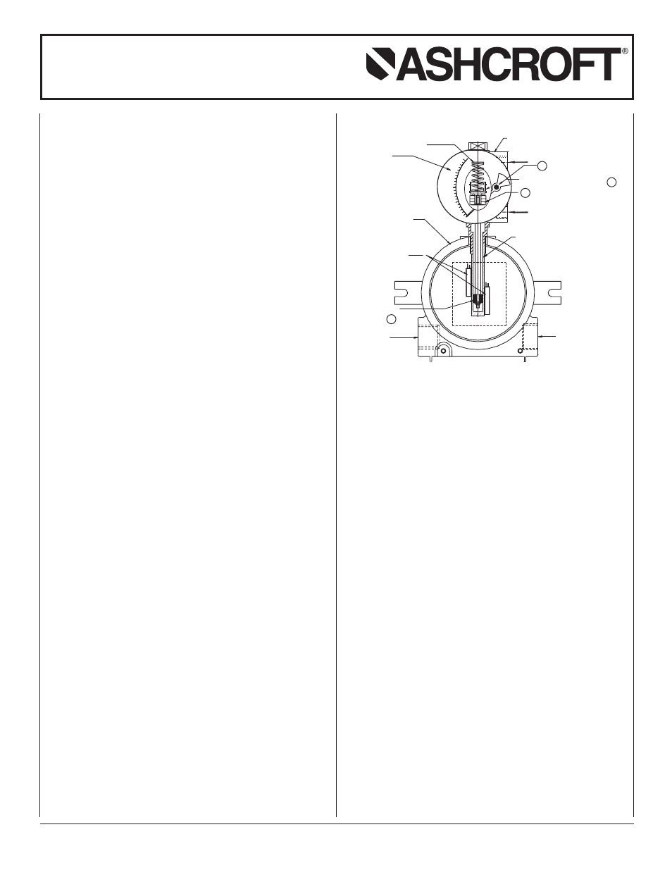
OPERATING PRINCIPLE
Variations in pressure between high and low ports is sensed by
a piston or diaphragm sensor
➀
which moves in proportion to
the pressure difference. A primary magnet
➁
is attached to the
sensor and moves with it in the same proportion. A rotary mag-
net
➂
with pointer is magnetically coupled with the primary
magnet, and is situated in an isolated cavity. Movement of rotary
magnet with pointer indicates differential pressure on the dial.
Process fluids are isolated from dial case and switch enclosure.
SWITCH: An auxiliary magnet
➃
situated in the tube extension
moves with the pressure sensors. Reed switches mounted on
the extension tube are activated due to interaction between
switch contacts and field of the auxiliary magnet. Switches can
be adjusted to open or close at preset points.
Note: The gauges are calibrated to give ±2%full scale accuracy
on ascending readings.
INSTALLATION
Depressurize the system and connect the high and low pres-
sure lines of your system to the “High” and “Low” ports of the
gauge, respectively.
Apply “High” and “Low” pressures simultaneously, to avoid dam-
age to the internal parts. If pressure exceeds the rated maxi-
mum pressure, “O” rings used on male connectors, and the
teflon seal inside the pressure chamber of piston instrument will
be damaged. In diaphragm instrument diaphragm may rupture.
If maximum operating pressure is within the allowable limit, but
the differential pressure exceeds gauge range, there will be no
damage to the gauge. Pointer will only go the extreme right end
of the scale.
EXPLOSION PROOF SWITCH INFORMATION
Switches and electrical connections are mounted in an explosion
proof enclosure with UL, CSA, FM and CENELEC approval. The
enclosure meets Class 1, Groups B, C, D, Class 2, Groups E, F,
G, Class, NEMA 7 & 9 and IP66. There are two
3
⁄
4
˝ electrical
condiut connections.
PRECAUTIONS
Do not connect “High” and “Low” ports to wrong pipe ends. Do
not subject the gauge to excessive vibration. The gauge is never
to be used in an area where a magnetic field is present. It may
affect readings.
As the gauge works on magnetic coupling principal, use only
non magnetic fittings, parts etc. in areas closer than 2˝ on all
sides, otherwise calibration will be affected.
Do not try to open any part of the gauge for any reason,
because if not reassembled properly, calibration and operation
will be affected.
SPST OR SPDT
MAGNET
3/4 NPT
CONDUIT PORT
AUXILIARY
SWITCH ENCLOSURE
REED SWITCH
ONE OR TWO
ADJUSTABLE
3/4 NPT
CONDUIT PORT
SENSING ELEMENT
PRESSURE EXTENSIONTUBE
HIGH PORT
PISTON OR DIAPHRAGM
RANGE SCALE
RANGE SPRING
D. P. GAUGE HOUSING
LOW PORT
0
5
10
15
20
25
2
1
3
4