Ashcroft H2 - Precision Pressure Transducer User Manual
Warning! read before installation, H2 pressure transmitter instruction sheet
H2 PRESSURE TRANSMITTER
INSTRUCTION SHEET
Ashcroft
®
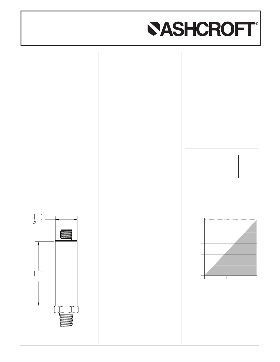
H2 Pressure Transmitter,
Typical Dimensions and Construction*
*
Dimensions and construction details may vary
based on product specified.
© 2013 Ashcroft Inc. All rights reserved. 250 East Main Street, Stratford, CT 06614 USA Tel: 203-378-8281, Fax: 203-385-0402 www.ashcroft.com
All sales subject to standard terms and conditions of sale. I&M011-10201-H2. Rev. 03/13
WARNING! READ
BEFORE INSTALLATION
1. GENERAL:
A failure resulting in injury or dam-
age may be caused by excessive
overpressure, excessive vibration or
pressure pulsation, excessive instru-
ment temperature, corrosion of the
pressure containing parts, or other
misuse. Consult Ashcroft Inc., Strat-
ford, Connecticut, USA before in-
stalling if there are any questions or
concerns.
2. OVERPRESSURE:
Pressure spikes in excess of the rated
overpressure capability of the trans-
ducer may cause irreversible electri-
cal and/or mechanical damage to
the pressure measuring and contain-
ing elements.
Fluid hammer and surges can destroy
any pressure transducer and must al-
ways be avoided. A pressure snubber
should be installed to eliminate the
damaging hammer effects. Fluid ham-
mer occurs when a liquid flow is
ƽ
ƽ
suddenly stopped, as with quick closing
solenoid valves. Surges occur when flow
is suddenly begun, as when a pump is
turned on at full power or a valve is
quickly opened.
Liquid surges are particularly damag-
ing to pressure transducers if the pipe
is originally empty. To avoid damaging
surges, fluid lines should remain full (if
possible), pumps should be brought up
to power slowly, and valves opened
slowly. To avoid damage from both fluid
hammer and surges, a surge chamber
should be installed.
Symptoms of fluid hammer and surge's
damaging effects:
• Pressure transducer exhibits an out-
put at zero pressure (large zero offset).
• Pressure transducer output remains
constant regardless of pressure
• In severe cases, there will be no output.
FREEZING:
Prohibit freezing of media in pressure
port. Unit should be drained (mount in
vertical position with electrical termi-
nation upward) to prevent possible
overpressure damage from frozen
media.
3. STATIC ELECTRICAL CHARGES:
Any electrical device may be suscepti-
ble to damage when exposed to static
electrical charges. To avoid damage to
the transducer observe the following:
• Operator/installer should follow the
proper ESD (electrostatic discharge)
protection procedures before han-
dling the pressure transducer.
• Ground the body of the transducer
BEFORE making any electrical
connections
• When disconnecting, remove the
ground LAST!
Note: The shield and drain wire in the
cable (if supplied) is not connected to
the transducer body, and is not a suit-
able ground.
65
2.56
22
.87
Mounting
The H2 transmitter requires no special
mounting hardware, and can be mounted
in any plane with negligible position error.
Although the unit can withstand normal
vibration without damage or significant
output effects, it is always good practice
to mount the transducer where there is
minimum vibration.
For units with NPT type pressure fittings
apply Teflon
®
tape (approximately 1
1
⁄
2
rev-
olutions) or an equivalent sealant to the
threads before installing.
When tightening, apply a wrench to the
hex wrench flats located just above the
pressure fitting. DO NOT tighten by using
a pipe wrench on the housing. Approximate
torque is 18.45 pounds force foot (25 Nm).
Power Supply
Power Supply Voltage
Output Signal Min Max
4-20mA 10Vdc* 32Vdc
0-5Vdc 13Vdc 32Vdc
0-10V 13Vdc 32Vdc
* For transmitters with 4-20mA output
signal, the minimum voltage at the termi-
nals is 10Vdc. However, the minimum
supply voltage should be calculated
using the following graph and formula.
Vmin = 10V+ (.022A x R
L
) (includes a 10% safety factor)
R
L
= R
S
+ R
W
R
L
= Loop Resistance (ohms)
R
S
= Sense Resistance (ohms)
R
W
= Wire Resistance (ohms)
10
1000
800
600
400
200
0
20
30
Operating
Region
Loop Supply Voltage (Vdc)
Loop Supply Voltage vs. Loop Resistance
L
o
o
p
R
e
s
is
ta
n
c
e
(
O
h
m
s
)