2 setting the baud rate, 3 setting the protocol, 4 setting the address – Videotec ULISSE User Manual
Page 24: 5 serial communication lines
EN - English - I
nstruc
tions manual
22
7.4.4 Setting the address
The ULISSE address can have a setting from 1 to 255.
Binary code is used to select the address, using the
8 dip-switches at the top right ("17 Appendix A - Dip-
switch address table", page 63).
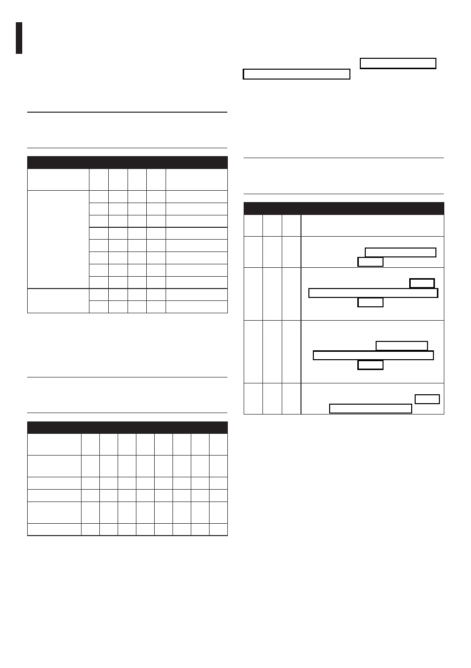
7.4.5 Serial communication lines
The product is designed with two RS485 serial
communication lines and one RS232 serial line, which
can have various settings according to the positions
of dip-switches 10 and 9 on the Serial and Address
selector.
j
When the dip-switch rocker is up it
represents the value 1 (ON) while if it is
down it represents the value 0 (OFF).
SERIAL AND ADDRESS, SERIAL LINE CONFIGURATION
DIP
10
DIP
9
DIP
8-1
Configuration
OFF OFF
-
It allows the one-way communication
on RS485-1 line ("7.4.5.1 RS485 RX line",
page 23).
OFF ON
-
It allows the full-duplex communication
according to RS422 standard ("7.4.5.2
RS422 line (RS485-1 RX and RS485-2 TX)",
page 23).
ON OFF
-
It allows the cascade configuration of
different devices. The signal is repeated
from every units ("7.4.5.3 RS485-1
line reception, RS485-2 line repetition",
page 23).
ON
ON
-
It allows the two-ways, half-duplex,
communication on RS485-1 line ("7.4.5.4
Tab. 10
7.4.2 Setting the baud rate
Dip-switches 4, 3 and 2 are used to set the
communication rate of the device according to the
table below.
Dip-switch number 1 is used to update the firmware.
During normal use, make sure the rocker is OFF
(DIP1=OFF).
j
When the dip-switch rocker is up it
represents the value 1 (ON) while if it is
down it represents the value 0 (OFF).
BAUDRATE SETTING
Description
DIP
4
DIP
3
DIP
2
DIP
1
Configuration
Baudrate
adjustment
OFF OFF OFF
-
300 baud
ON OFF OFF
-
600 baud
OFF ON OFF
-
1200 baud
ON
ON OFF
-
2400 baud
OFF OFF ON
-
4800 baud
ON OFF ON
-
9600 baud
OFF ON
ON
-
19200 baud
ON
ON
ON
-
38400 baud
Firmware update
-
-
-
ON
Set up enabled
-
-
-
OFF
Set up disabled
Tab. 08
7.4.3 Setting the protocol
Video positioning systems with the ULISSE line can be
controlled by a range of protocols.
j
When the dip-switch rocker is up it
represents the value 1 (ON) while if it is
down it represents the value 0 (OFF).
PROTOCOL SETTING
DIP
8
DIP
7
DIP
6
DIP
5
DIP
4
DIP
3
DIP
2
DIP
1
MACRO
(VIDEOTEC)
OFF OFF OFF OFF OFF ON ON ON
PANASONIC
OFF OFF OFF ON OFF ON OFF OFF
PELCO D
OFF OFF OFF OFF ON OFF OFF ON
AMERICAN
DYNAMICS
OFF OFF OFF OFF ON ON ON OFF
VISTA
OFF OFF OFF ON OFF OFF ON ON
Tab. 09