3 fixing the top unit, 4 configuration, 1 dip-switch configuration – Videotec ULISSE User Manual
Page 23: 3 fixing the top unit 7.4 configuration
EN - English - I
nstruc
tions manual
21
7.4 Configuration
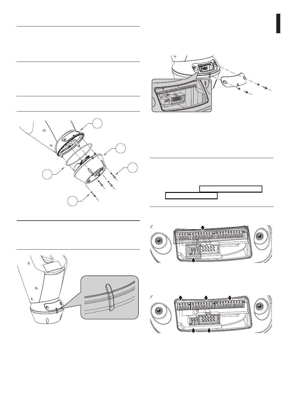
Before powering the device it must be configured
correctly by setting the dip-switches inside the
configuration window. Open the window by undoing
the screws as shown in the illustration:
Fig. 38
7.4.1 Dip-switch configuration
The following diagram represents the position of
the dip-switches when the configuration window is
opened.
j
When the dip-switch rocker is up it
represents the value 1 (ON) while if it is
down it represents the value 0 (OFF). This
rule is valid for all dip-switches except for
in the section "7.4.6 Serial terminations/
connections", page 24 where they are
inverted.
Rocker up = ON = 1
Rocker down = OFF = 0
Rocker up = OFF = 0
Rocker down = ON = 1
Fig. 39
Baudrate
Protocol Serial and Address
Termination of
RS485 lines
RS232 serial
connector
Fig. 40
7.3 Fixing the top unit
j
Inside the bottom cover there is a sachet
containing desiccant that is used to prevent
moisture formation in the base and near
the connector boards. Remove the sachet
during installation.
Attach the top unit (01) to the base (02) using
the attachment screws (03), supplied with the
corresponding seals (04). Make sure the base seal is
present and in good condition (05).
h
Fasten with tightening
torque of 4Nm.
01
02
03
05
04
Fig. 36
j
There is only one way to anchor the base
with the top part. Align the tabs on the
sides to make sure the parts are positioned
correctly.
Fig. 37