2 alarm contact and relay connections – Videotec ULISSE User Manual
Page 22
EN - English - I
nstruc
tions manual
20
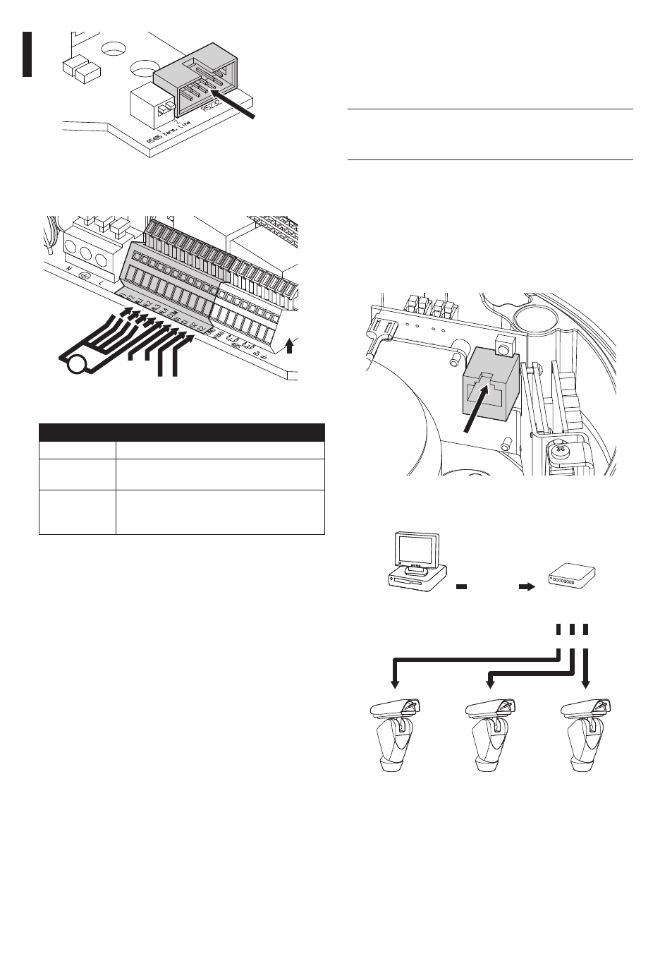
7.2.5 Connecting the Ethernet cable
(for IP board version only)
To connect the net cable a UTP, Category 5E or
superior, 4 pair with a max length of 100m. is needed.
j
Telemetry transmission and video signal
pass through the Ethernet cable. Do not
connect cable RS485 and the video cable.
Crimp the RJ45 connector on the ethernet cable.
Crimping should be straight-through if passing via
a hub or switch while it should be crossover if you
are connecting directly to the PC for the necessary
checks.
Connect the crimped net cable to connector RJ45
located on the base of the unit.
Fig. 34
The example below shows a typical installation.
Hub / Switch
Personal
Computer
UTP cat 5E
UTP cat 5E
Fig. 35
RS232
Fig. 32
7.2.4.2 Alarm contact and relay connections
Signal
Vdc
O1 C1
O2 C2
+
V
Fig. 33
TERMINALS
DESCRIPTION
F1-F2
Additional lines
O1-C1 and
O2-C2
Clean output contacts, can be activated by
alarm or by user control
AL1, AL2, AL3,
AL4 and COM
Live controlled alarm inputs referring to
common COM
Tab. 07