Eviewing, Ront, Uttons – Red Lion PAXDR User Manual
Page 8: Isplay, 3 input wiring, See appropriate plug-in card bulletin for details
8
5.0 R
EVIEWING
THE
F
RONT
B
UTTONS
AND
D
ISPLAY
Totalizer
Display
Annunciators*
Setpoint Alarm
Annunciators
RST
DSP
PAR
F1
F2
A
C
B
SP1
SP3
SP2
SP4
8.8.8.8.8.8.
List B Active
Indicator
* Totalizer A, B, and C are locked out in Factory Settings.
** Factory setting for the F1 F2 and RST keys is NO mode.
Advances selected digit location in parameter values
Reset (Function key) **
RST
Decrement selected parameter value or selections
Function key 2; hold for 3 seconds for Second Function 2 **
F2
Increment selected parameter value or selections
Function key 1; hold for 3 seconds for Second Function 1 **
F1
Store selected parameter and index to next parameter
Access Programming Mode
PAR
Quit programming and return to Display Mode
Index display through the selected displays.
DSP
PROGRAMMING MODE OPERATION
DISPLAY MODE OPERATION
KEY
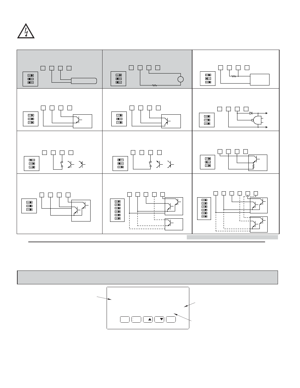
4.3 INPUT WIRING
CAUTION: Sensor input common is NOT isolated from user input common. In order to preserve the safety of the meter application, the sensor input
common must be suitably isolated from hazardous live earth referenced voltage; or input common must be at protective earth ground potential. If not,
hazardous voltage may be present at the User Inputs and User Input Common terminals. Appropriate considerations must then be given to the potential
of the user input common with respect to earth ground; and the common of the isolated plug-in cards with respect to input common.
3
4
5
MAGNETIC PICKUP
6
+12V
COMM
INPUT
A
INPUT
B
3
1
2
ON
6
3
4
5
to 2.5 mA MAX.
Resistor to limit current
AC
+12V
COMM
INPUT
A
INPUT
B
3
2
1
ON
4
3
5
6
2.2K
Ω
COMM
+12V
INPUT
B
INPUT
A
2
1
3
ON
NPN O.C.
3
4
5
6
COMM
+12V
INPUT
A
INPUT
B
1
2
3
ON
PNP O.C.
3
4
5
6
+12V
COMM
INPUT
A
INPUT
B
2
1
3
ON
ON
4
2
3
1
3
5
6
+5V
COMM
DIODE
+12V
COMM
INPUT
B
INPUT
A
3
4
5
6
INPUT
A
INPUT
B
COMM
+12V
2
1
3
ON
6
3
4
5
INPUT
A
INPUT
B
+12V
COMM
1
2
3
ON
3
4
5
6
INPUT
A
INPUT
B
+12V
COMM
2
1
3
ON
AC Inputs From Tach Generators, Etc.
Input A
Two Wire Proximity, Current Source
Input A
Magnetic Pickup
Input A
Current Sourcing Output
Input A
Interfacing With TTL
Input A
Current Sinking Output
Input A
Switch or Isolated Transistor; Current Sink
Input A
6
3
4
5
NPN O.C.
COMM
+12V
INPUT
B
INPUT
A
3
2
1
ON
Current Sink Output; Quad/Direction
Totalizer A
Switch or Isolated Transistor; Current Source
Input A
Emitter Follower; Current Source
Input A
6
3
4
5
NPN O.C.
NPN O.C.
7
Rate B
Totalizer A
+12V
COMM
USER 1
INPUT
A
INPUT
B
4
1
2
3
6
5
ON
3
4
5
6
NPN O.C.
Totalizer A
7
8
NPN O.C.
Totalizer B
+12V
COMM
INPUT
A
INPUT
B
3
2
1
ON
4
5
6
USER 1
USER 2
Current Sink Output; Quad/Direction
Totalizer A
& Rate B
Totalizer A &
Totalizer B
Current Sink Output; Quad/Direction
If you are wiring Input B, connect signal to Terminal 6 instead of 5, and set DIP switches 4, 5, and 6 to the positions shown for 1, 2, and 3.
If using Totalizer B, then wire signal to 6, and
Quad/Direction to 8. Set switch positions 4, 5,
and 6 as shown for 1, 2, and 3.
User Input Jumper
in Sink Position
User Input Jumper
in Sink Position
Shaded areas not recommended for counting applications.
4.4 SETPOINT (ALARMS) WIRING
4.5 SERIAL COMMUNICATION WIRING
4.6 ANALOG OUTPUT WIRING
See appropriate plug-in card bulletin for details.