9 module 9 - f, Actory, Ervice – Red Lion PAXDR User Manual
Page 26: Perations, Troubleshooting, D-lev, Fcs pro, Code
26
d-LEV
Display
Intensity Level
PAR
9-FCS
Pro
Factory
Service Code
COdE
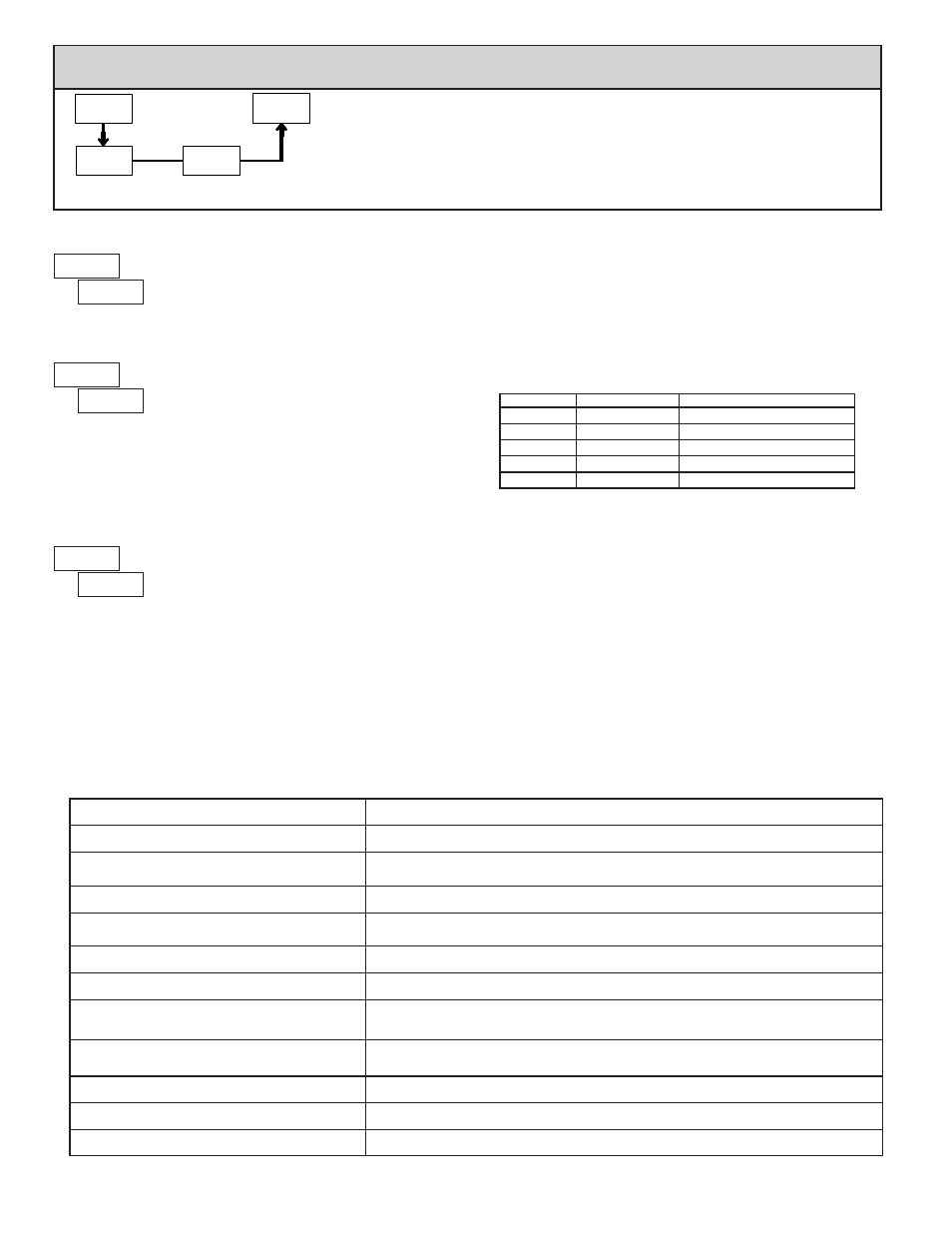
PARAMETER MENU
RESTORE FACTORY DEFAULTS
Use the arrow keys to display
and press PAR.
The meter will display
and then return to
.
Press DSP key to return to the Display Mode. This will
overwrite all user settings with the factory settings.
Pressing the PAR and DSP keys at the same time on power-up will load the
factory settings and display
. This allows operation in the event of a
memory failure or corrupted data. Immediately press RST key and reprogram
the meter. If the meter is powered down again before pressing the RST key, the
existing dynamic data will not be overwritten.
6.9 MODULE 9 - F
ACTORY
S
ERVICE
O
PERATIONS
(
)
Enter the desired Display Intensity Level (0-15) by
using the arrow keys. The display will actively dim or
brighten as the levels are changed. This parameter also
appears in Quick Programming Mode when enabled.
DISPLAY INTENSITY LEVEL
CALIBRATION
TROUBLESHOOTING
For further assistance, contact technical support at the appropriate company numbers listed.
PROBLEM
REMEDIES
NO DISPLAY
CHECK: Power level, power connections
PROGRAM LOCKED-OUT
CHECK: Active (lock-out) user input
ENTER: Security code requested
CERTAIN DISPLAYS ARE LOCKED OUT
CHECK: Module 3 programming
INCORRECT DISPLAY VALUE or NOT
COUNTING
CHECK: Input wiring, DIP switch setting, input programming, scale factor calculation,
input signal level, user input jumper, lower input signal frequency
USER INPUT NOT WORKING CORRECTLY
CHECK: User input wiring, user input jumper, user input being used for signal, Module 2
OUTPUT DOES NOT WORK
CHECK: Corresponding plug-in card installation, output configuration, output wiring
JITTERY DISPLAY
CHECK: Wiring is per EMC installation guidelines, input signal frequency, signal quality,
scaling, update time, DIP switch setting
“
” DISPLAYED
CHECK: Lower input signal frequency, reduce scaling values (display capacity exceeded).
Divide by 0 condition exists for Display C calculation.
MODULES or PARAMETERS NOT ACCESSIBLE
CHECK: Corresponding plug-in card installation, related controlling parameter selected
ERROR CODE (
)
PRESS: Reset key (if unable to clear contact factory.)
SERIAL COMMUNICATIONS
CHECK: Wiring, connections, meter and host settings
Analog Output Card Calibration
Before starting, verify that a precision meter with an accuracy of 0.05% or
better (voltmeter for voltage output and/or current meter for current output) is
connected and ready. Then perform the following procedure:
1. Use the arrow keys to display
and press PAR.
2.
is displayed. Use the arrow keys to select
and press PAR.
3. Using the chart below, step through the five selections to be calibrated. At
each prompt, use the PAXDR arrow keys to adjust the output so that the
external meter display matches the selection being calibrated. When the
external reading matches, or if the range is not being calibrated, press PAR.
SELECTION
EXTERNAL METER
ACTION
0.00
Adjust if necessary, press PAR
4.00
Adjust if necessary, press PAR
20.00
Adjust if necessary, press PAR
0.00
Adjust if necessary, press PAR
10.00
Adjust if necessary, press PAR
4. When
appears, press PAR twice and remove the external meters .
The only item in the PAXDR meter that can be calibrated
is the Analog Output. If the meter appears to be indicating
incorrectly or inaccurately, refer to the Troubleshooting
section.
When Analog Out recalibration is required (generally every 2 years), it
should be performed by qualified technicians using appropriate equipment.
Calibration does not change any user programmed parameters.
Calibration may be aborted by disconnecting power to the meter before
exiting Module 9. In this case, the existing calibration settings remain in effect.
Note: Allow a 30 minute warm-up period before starting calibration.