8 module 8 - a, Pro 8-ana asin, Type an-lo an-hi – Red Lion PAXDR User Manual
Page 25: Nalog, Utput, Arameters
25
COMMUNICATION FORMAT
Data is transferred from the meter through a serial communication channel.
In serial communications, the voltage is switched between a high and low level
at a predetermined rate (baud rate) using ASCII encoding. The receiving device
reads the voltage levels at the same intervals and then translates the switched
levels back to a character.
The voltage level conventions depend on the interface standard. The table
lists the voltage levels for each standard.
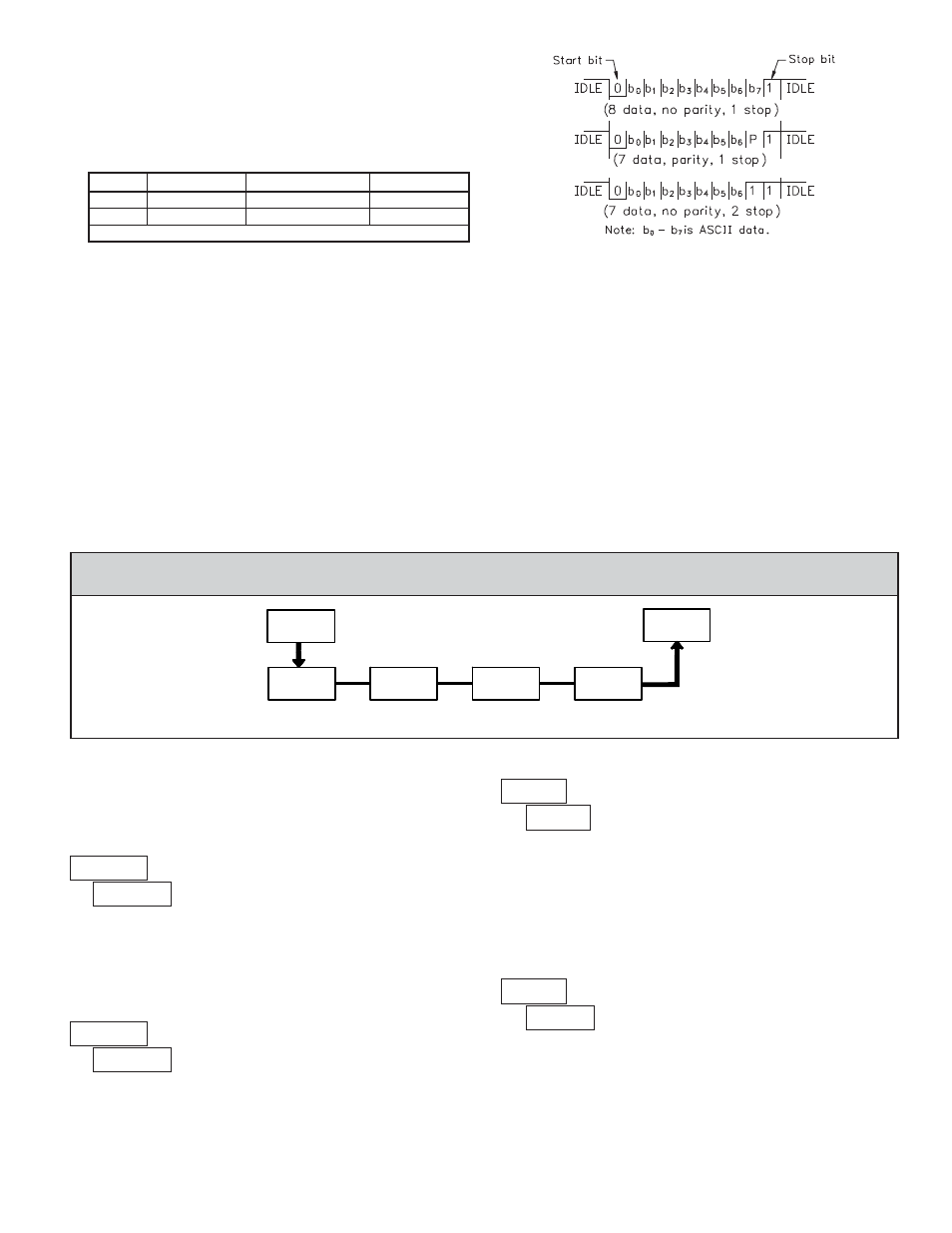
Data is transmitted one byte at a time with a variable idle period between
characters (0 to
). Each ASCII character is “framed” with a beginning start bit,
an optional parity bit and one or more ending stop bits. The data format and
baud rate must match that of other equipment in order for communication to
take place. The figures list the data formats employed by the meter.
Start bit and Data bits
Data transmission always begins with the start bit. The start bit signals the
receiving device to prepare for reception of data. One bit period later, the least
significant bit of the ASCII encoded character is transmitted, followed by the
remaining data bits. The receiving device then reads each bit position as they are
transmitted.
Parity bit
After the data bits, the parity bit is sent. The transmitter sets the parity bit to
a zero or a one, so that the total number of ones contained in the transmission
(including the parity bit) is either even or odd. This bit is used by the receiver
to detect errors that may occur to an odd number of bits in the transmission.
However, a single parity bit cannot detect errors that may occur to an even
number of bits. Given this limitation, the parity bit is often ignored by the
receiving device. The PAX meter ignores the parity bit of incoming data and
sets the parity bit to odd, even or none (mark parity) for outgoing data.
Stop bit
The last character transmitted is the stop bit. The stop bit provides a single bit
period pause to allow the receiver to prepare to re-synchronize to the start of a
new transmission (start bit of next byte). The receiver then continuously looks
for the occurrence of the start bit. If 7 data bits and no parity is selected, then 2
stop bits are sent from the PAX meter.
Character Frame Figure
LOGIC
RS232*
RS485*
INTERFACE STATE
1
TXD,RXD; -3 to -15 V
a-b < -200 mV
mark (idle)
0
TXD,RXD; +3 to +15 V
a-b > +200 mV
space (active)
* Voltage levels at the Receiver
PAR
Pro
8-AnA
ASIN
Analog
Type
tYPE
AN-LO
AN-HI
Analog
Assignment
Analog Low
Scale Value
Analog High
Scale Value
ANALOG ASSIGNMENT
ANALOG LOW SCALE VALUE
ANALOG HIGH SCALE VALUE
PARAMETER MENU
ANALOG TYPE
Enter the analog output type. For voltage output use terminals 16 and 17. For
current output use terminals 18 and 19. Only one range can be used at a time.
Select the display that the analog output is to follow:
Enter the display value within the selected Analog Assignment that
corresponds to the high limit of the type selected.
The decimal point is determined by the decimal point setting of the assigned
totalizer or rate. The scale value can not be set to read values with more than 6
digits. Reverse acting output is possible by reversing the scaling values.
to
to
Module 8 is the programming for the analog output parameters. To have an
analog output signal, an analog output plug-in card needs to be installed (See
Ordering Information).
SELECTION
RANGE
0 to 20 mA
4 to 20 mA
0 to 10 V
Enter the display value within the selected Analog Assignment that
corresponds to the low limit of the type selected.
The decimal point is determined by the decimal point setting of the assigned
totalizer or rate. The scale value can not be set to read values with more than 6
digits. Reverse acting output is possible by reversing the scaling values.
6.8 MODULE 8 - A
NALOG
O
UTPUT
P
ARAMETERS
(
)
= Rate C Value
= Totalizer C Value
= Rate B Value
= Totalizer B Value
= Rate A Value
= Totalizer A Value