2 module 2 - u – Red Lion PAXDR User Manual
Page 13
13
PRINT REQUEST
PRINT REQUEST AND RESET DISPLAYS
RESET DISPLAY
When activated (momentary action), the shown display is reset.
EXCHANGE PARAMETER LISTS
Two lists of values are available for
,
,
,
,
,
,
,
,
. The two lists are named
and
. If a user
input is used to select the list then
is selected when the user input is not
active and
is selected when the user input is active (maintained action).
If a front panel key is used to select the list, then the list will toggle for each key
press (momentary action). The meter will suspend ALL operations for
approximately 1 msec. while the new values are loaded. The display will
indicate which list is active when the list is changed or when entering any
Programming Mode. In addition, the decimal point to the right of digit 1 is
displayed when List B is active.
To program the values for
and
, first complete the programming
of all the parameters. Exit programming and switch to the other list. Re-enter
programming and enter the values for
,
,
,
,
,
,
,
,
. If any other parameters are changed then the other list
values must be reprogrammed.
The meter issues a block print through the serial port when activated. The
data transmitted during the print request is configured in Module 7. If the user
input is still active after the transmission is complete (about 100 msec.), an
additional transmission will occur. Only one transmission will take place with
each function key depression. This selection will only function when a serial
communications Plug-in card is installed in the meter.
ADVANCE DISPLAY
When activated (momentary action), the display advances to the next display
that is not locked out from the Display Mode.
The meter issues a block print through the serial port when activated just like
the Print Request function. In addition, when activated (momentary action), the
meter performs a reset of the totalizer displays configured as
. The print
aspect of this action only functions when a serial communication plug-in card
is installed. The reset action functions regardless.
DISPLAY
DESCRIPTION
FACTORY
Totalizer A
Totalizer B
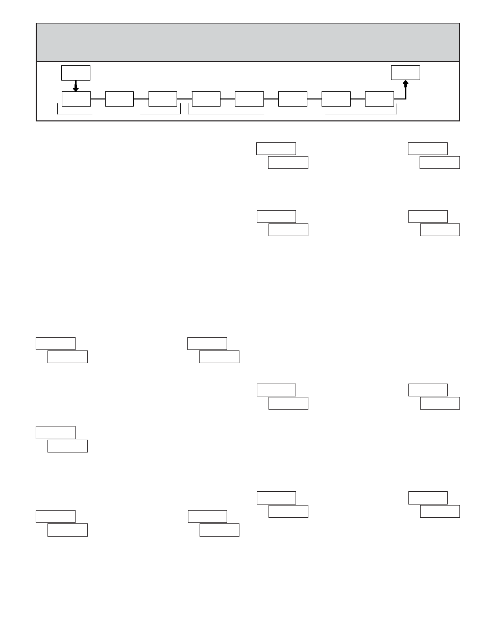
6.2 MODULE 2 - U
SER
I
NPUT
AND
F
RONT
P
ANEL
F
UNCTION
K
EY
P
ARAMETERS
(
)
2-FNC
USr-2
USr-1
USr-3
SC-F1
F1
F2
rSt
SC-F2
PAR
Pro
FUNCTION KEYS
USER INPUTS
PARAMETER MENU
Module 2 is the programming for rear terminal user inputs and front panel
function keys.
Three rear terminal user inputs are individually programmable to perform
specific meter control functions. While in the Display Mode, the function is
executed when the user input transitions to the active state. (Refer to the user
input specifications for active state response times.) Certain user input functions
are disabled while the meter is in “full” Programming Mode.
Three front panel function F1, F2 and RST keys are also individually
programmable to perform specific meter control functions. While in the Display
Mode, the primary function is executed when the key is pressed. Holding the
F1
and F2 function keys for three seconds executes a secondary function. It is
possible to program a secondary function without a primary function. The front
panel key functions are disabled while the meter is in Programming Mode.
In most cases, if more than one user input and/or function key is programmed
for the same function, the maintained (level trigger) actions will be performed
while at least one of those user inputs or function keys are activated. The
momentary (edge trigger) actions are performed every time any of those user
inputs or function keys transition to the active state.
Some of the user functions have a sublist of parameters. The sublist is
accessed when PAR is pressed at the listed function. The function will only be
performed for the parameters entered as
. If a user input or function key is
configured for a function with a sublist, then that sublist will need to be scrolled
through each time to access the following user inputs or function keys
parameters.
NO FUNCTION
With this selection, NO function is performed. This is the factory setting for
all user inputs and function keys.
NOTE: When a user input is used to accept a quad or directional input
signal, then that user input should be programmed for NO function.
PROGRAMMING MODE LOCK-OUT
Programming Mode is locked-out, as long as activated
(maintained action). In Module 3, certain parameters can
be setup where they are still accessible during
Programming Mode Lockout. A security code can be
configured to allow complete programming access during user input lockout.
Function keys should not be programmed for
.