Sending serial commands and data, Command chart, Command string construction – Red Lion PAXDR User Manual
Page 23: Register identification chart, Command string examples, Transmitting data to the meter, Transmitting data from the meter, Full transmission, Abbreviated transmission, Meter response examples
23
SENDING SERIAL COMMANDS AND DATA
When sending commands to the meter, a string containing at least one
command character must be constructed. A command string consists of a
command character, a value identifier, numerical data (if writing data to the
meter) followed by a command terminator character * or $.
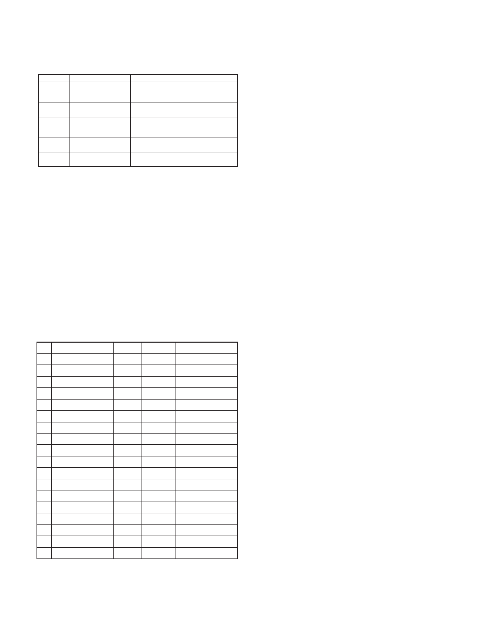
Command Chart
Command
Description
Notes
N
Node (Meter) Address
Specifier
Address a specific meter. Must be
followed by two digit node address. Not
required when address = 00.
T
Transmit Value (read)
Read a register from the meter. Must be
followed by register ID character.
V
Value change (write)
Write to register of the meter. Must be
followed by register ID character and
numeric data.
R
Reset
Reset a register or output. Must be
followed by register ID character
P
Block Print Request
(read)
Initiates a block print output. Registers
are defined in programming.
Command String Construction
The command string must be constructed in a specific sequence. The meter
does not respond with an error message to invalid commands. The following
procedure details construction of a command string:
1. The first characters consist of the Node Address Specifier (N) followed by a
2 character address number. The address number of the meter is programmable.
If the node address is 0, this command and the node address itself may be
omitted. This is the only command that may be used in conjunction with other
commands.
2. After the optional address specifier, the next character is the command
character.
3. The next character is the Register ID. This identifies the register that the
command affects. The P command does not require a Register ID character.
It prints according to the selections made in print options.
4. If constructing a value change command (writing data), the numeric data is
sent next.
5. All command strings must be terminated with the string termination
characters * or $. The meter does not begin processing the command string
until this character is received. See Timing Diagram figure for differences
between terminating characters.
Register Identification Chart
ID
VALUE DESCRIPTION
REGISTER
NAME
1
COMMAND
2
TRANSMIT DETAILS
3
A
Rate A
RTA
T
5 digit, positive only
B
Rate B
RTB
T
5 digit, positive only
C
Rate C
RTC
T
4 negative, 5 positive
D
Total A
TOA
T, V, R
6 digit (V), 8 digit (T)
E
Total B
TOB
T, V, R
6 digit (V), 8 digit (T)
F
Total C
TOC
T, R
8 digit
G
Scale Factor A
SFA
T, V
6 digit, positive only
H
Scale Factor B
SFB
T, V
6 digit, positive only
I
Scale Factor C
SFC
T, V
6 digit, positive only
J
Count Load A
LDA
T, V
5 negative, 6 positive
K
Count Load B
LDB
T, V
5 negative, 6 positive
M
Setpoint 1
SP1
T, V, R
5 negative, 6 positive
O
Setpoint 2
SP2
T, V, R
5 negative, 6 positive
Q
Setpoint 3
SP3
T, V, R
5 negative, 6 positive
S
Setpoint 4
SP4
T, V, R
5 negative, 6 positive
U
Auto/Manual Register
MMR
T, V
0 - auto, 1 - manual
W
Analog Output Register
AOR
T, V
0 - 4095 normalized
X
Setpoint Register
SOR
T, V
0 - not active, 1 - active
1
. Register Names are also used as Register Mnemonics during full transmission.
2
. The registers associated with the P command are set up in Print Options (Module 7).
3
. Unless otherwise specified, the Transmit Details apply to both T and V
Commands.
Command String Examples:
1. Address = 17, Write 350 to Setpoint 1
String: N17VM350$
2. Address = 5, Read Rate A value, response time of 50 - 100 msec. min.
String: N05TA*
3. Address = 0, Reset Setpoint 4 output
String: RS*
Transmitting Data To the Meter
Numeric data sent to the meter must be limited to Transmit Details listed in
the Register Identification Chart. Leading zeros are ignored. Negative numbers
must have a minus sign. The meter ignores any decimal point and conforms the
number to the scaled resolution. (ie. The meter’s scaled decimal point position
is set for 0.0 and 25 is written to a register. The value of the register is now 2.5.
In this case, write a value of 250 to equal 25.0).
Note: Since the meter does not issue a reply to value change commands, follow
with a transmit value command for readback verification.
Transmitting Data From the Meter
Data is transmitted from the meter in response to either a transmit command
(T), a print block command (P) or User Function print request. The response
from the meter is either a full field transmission or an abbreviated transmission.
The meter response is established in Module 7.
Full Transmission
These characters only appear in the last line of a block print.
The first two characters transmitted (bytes 1 and 2) are the unit address. If the
address assigned is 00, two spaces are substituted. A space (byte 3) follows the
unit address field. The next three characters (bytes 4 to 6) are the register
mnemonic. The numeric data is transmitted next.
The numeric field (bytes 7 to 18) is 12 characters long. When the requested
value exceeds eight digits for total values or five digits for rate values, an *
(used as an overflow character) replaces the space in byte 7. Byte 8 is always a
space. The remaining ten positions of this field (bytes 9 to 18) consist of a minus
sign (for negative values), a floating decimal point (if applicable), and eight
positions for the requested value. The data within bytes 9 to 18 is right-aligned
with leading spaces for any unfilled positions.
The end of the response string is terminated with
(byte 20). When a block print is finished, an extra
22), and
Abbreviated Transmission
These characters only appear in the last line of a block print.
The abbreviated response suppresses the address and register mnemonics,
leaving only the numeric part of the response.
Meter Response Examples:
1. Address = 17, full field response, Rate A = 875
17 RTA 875
2. Address = 0, full field response, Setpoint 2 = -250.5
SP2 -250.5
3. Address = 0, abbreviated response, Setpoint 2 = 250, last line of block print
250
Byte
Description
1-12
12 byte data field, 10 bytes for number, one byte for sign, one byte
for decimal point
13
14
15
16
17
23
22
21
20
3 byte Register Mnemonic field
4-6
3
12 byte numeric data field: 10 bytes for number, one byte for sign, one
byte for decimal point
7-18
2 byte Node (Meter) Address field [00-99]
1, 2
19
Description
Byte