Command response time, Timing diagrams – Red Lion PAXDR User Manual
Page 24
24
Auto/Manual Mode Register (MMR) ID: U
This register sets the controlling mode for the outputs. In Auto Mode (0) the
meter controls the setpoint and analog output. In Manual Mode (1) the outputs
are defined by the registers SOR and AOR. When transferring from auto mode
to manual mode, the meter holds the last output value (until the register is
changed by a write). Each output may be independently changed to auto or
manual. In a write command string (VU), any character besides 0 or 1 in a field
will not change the corresponding output mode.
U abcde
e = Analog Output
d = SP4
c = SP3
b = SP2
a = SP1
Example: Address = 0, place SP4 and Analog in manual mode
String: VU00011*
Analog Output Register (AOR) ID: W
This register stores the present signal value of the analog output. The range
of values of this register is 0 to 4095, which corresponds to the analog output
range per the following chart:
*Due to the absolute
accuracy rating and
resolution of the output
card, the actual output
signal may differ 0.15% FS
from the table values. The
output signal corresponds
to the range selected (0-20
mA, 4-20 mA or 0-10 V).
Writing to this register (VW) while the analog output is in the Manual Mode
causes the output signal level to update immediately to the value sent. While in
the Automatic Mode, this register may be written to, but it has no effect until the
analog output is placed in the manual mode. When in the Automatic Mode, the
meter controls the analog output signal level. Reading from this register (TW)
will show the present value of the analog output signal.
Example: Address = 0, Analog output previously programmed for Manual Mode
String: VW2047* will result in an output of 10.000 mA, 12.000 mA or
5.000 V depending on the range selected.
Setpoint Output Register (SOR) ID: X
This register stores the states of the setpoint outputs. Reading from this
register (TX) will show the present state of all the setpoint outputs. A “0” in the
setpoint location means the output is off and a “1” means the output is on.
X abcd
d = SP4
c = SP3
b = SP2
a = SP1
In Automatic Mode, the meter controls the setpoint output state. In Manual
Mode, writing to this register (VX) will change the output state. Sending any
character besides 0 or 1 in a field or if the corresponding output was not first in
manual mode, the corresponding output value will not change. (It is not
necessary to send least significant 0s.)
Example: Address = 0, SP1 and SP2 previously programmed for Manual Mode
String: VX10* will result in output 1 on and output 2 off.
10.000
20.000
9.9975
19.996
5.000
12.000
0.0025
4.004
0.000
4.000
0-10V
4-20 mA
20.000
4095
19.995
4094
10.000
2047
Output Signal*
Register Value
0.005
1
0.000
0
0-20 mA
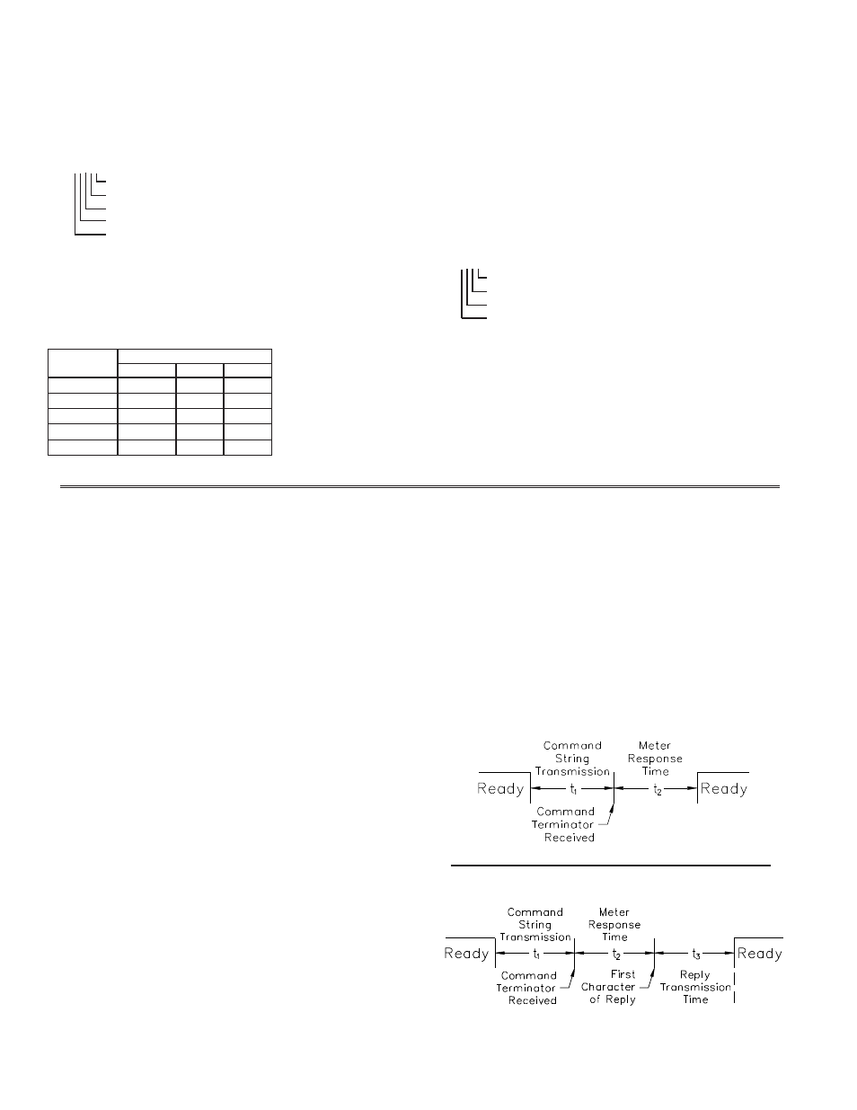
COMMAND RESPONSE TIME
The meter can only receive data or transmit data at any one time (half-duplex
operation). During RS232 transmissions, the meter ignores commands while
transmitting data, but instead uses RXD as a busy signal. When sending
commands and data to the meter, a delay must be imposed before sending
another command. This allows enough time for the meter to process the
command and prepare for the next command.
At the start of the time interval t
1
, the computer program prints or writes the
string to the com port, thus initiating a transmission. During t
1
, the command
characters are under transmission and at the end of this period, the command
terminating character (* or $) is received by the meter. The time duration of t
1
is dependent on the number of characters and baud rate of the channel.
t
1
= (10 times the # of characters) / baud rate
At the start of time interval t
2
, the meter starts the interpretation of the
command and when complete, performs the command function. This time
interval t
2
varies (See Timing Diagrams). If no response from the meter is
expected, the meter is ready to accept another command.
If the meter is to reply with data, the time interval t
2
is controlled by the use
of the command terminating character. The ‘*’ terminating character results in
a response time window of 50 msec. minimum and 100 msec. maximum. This
allows sufficient time for the release of the sending driver on the RS485 bus.
Terminating the command line with ‘$’ results in a response time window (t
2
)
of 2 msec. minimum and 50 msec. maximum. The faster response time of this
terminating character requires that sending drivers release within 2 msec. after
the terminating character is received.
At the beginning of time interval t
3
, the meter responds with the first
character of the reply. As with t
1
, the time duration of t
3
is dependent on the
number of characters and baud rate of the channel. At the end of t
3
, the meter is
ready to receive the next command.
t
3
= (10 times the # of characters) / baud rate
The maximum serial throughput of the meter is limited to the sum of the
times t
1
, t
2
and t
3
.
NO REPLY FROM METER
RESPONSE FROM METER
Timing Diagrams
COMMAND
COMMENT
PROCESS TIME (t
2
)
R
Reset
2-50 msec.
V
Write
100-200 msec.
T
Transmit
2-50 msec. for $
50-100 msec. for *
P
2-50 msec. for $
50-100 msec. for *
SERIAL TIMING