Red Lion PAXDR User Manual
Page 11
11
RATE A INPUT VALUE FOR SCALING POINT 1
RATE A DISPLAY VALUE FOR SCALING POINT 1
Non-linear Application – Up to 10 Scaling Points
Non-linear processes may utilize up to nine segments (ten scaling points) to
provide a piece-wise linear approximation representing the non-linear function.
The Rate display will be linear throughout each individual segment (i.e.
between sequential scaling points). Thus, the greater the number of segments,
the greater the conformity accuracy.
About Scaling Points
Each Scaling Point is specified by two programmable parameters: A desired
Rate Display Value (
) and a corresponding Rate Input Value (
). Scaling
points are entered sequentially in ascending order of Rate Input Value.
Two scaling points must be programmed to define the upper and lower
endpoints of the first linear segment. Setting
, automatically factory sets
the first scaling point to 0.0 for typical single segment, zero based applications.
When multiple segments are used, the upper scaling point for a given segment
becomes the lower scaling point for the next sequential segment. Thus, for each
additional segment used, only one additional scaling point must be programmed.
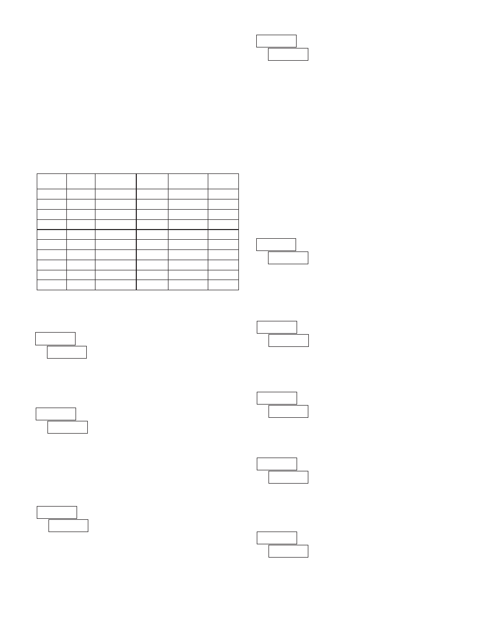
The following chart shows the Scaling Points, the corresponding Parameter
mnemonics, and the Factory Default Settings for each point.
SEGMENT
SCALING
POINT
DISPLAY
PARAMETER
DISPLAY
DEFAULT
INPUT
PARAMETER
INPUT
DEFAULT
1
000000
00000.0
1
2
001000
01000.0
2
3
002000
02000.0
3
4
003000
03000.0
4
5
004000
04000.0
5
6
005000
05000.0
6
7
006000
06000.0
7
8
007000
07000.0
8
9
008000
08000.0
9
10
009000
09000.0
Confirm the Rate A Display Value for the first Scaling Point is 0. This
parameter is automatically set to 0 and does not appear when
. (See Note)
Confirm the Rate A Input Value for the first Scaling Point is 0.0. (See Note)
Note: For all linear and most non-linear applications, the Scaling Point 1
parameters (
and
) should be set to 0 and 0.0 respectively. Consult
the factory before using any non-zero values for Scaling Point 1. These
parameters are automatically set to 0 and do not appear when
.
RATE A DISPLAY VALUE FOR SCALING POINT 2
Enter the desired Rate A Display Value for the second Scaling Point by using
the arrow keys.
to
to
to
RATE A INPUT VALUE FOR SCALING POINT 2
Enter the corresponding Rate A Input Value for the second Scaling Point by
using the arrow keys. Rate Input values for scaling points can be entered by
using the Key-in or the Applied method described below.
Key-in Method:
Enter the Rate Input value (
) that corresponds to the entered Rate Display
value (
) by pressing the F1 or F2 keys. This value is always in pulses per
second (Hz).
Applied Method:
Apply an external rate signal to the appropriate input terminals. At the Rate
Input Value (
) press and hold the F1 and F2 keys at the same time. The
applied input frequency (in Hz) will appear on the display. (To verify correct
reading wait for at least the length of the Low Update Time. Then press and
hold the F1 and F2 keys at the same time again. The new value should be ±
0.1% of the previous entered value.) Press PAR to enter the displayed
frequency as the Rate Input value. To prevent the displayed value from being
entered, press DSP. This will take the meter out of Programming Mode and the
previous Rate Input value will remain.
Rounding values other than one will round the Rate display to the nearest
increment selected (e.g. rounding of ‘5’ causes 122 to round to 120 and 123 to
round to 125). Rounding starts at the least significant digit of the Rate display.
RATE A DISPLAY ROUNDING
to
RATE B LINEARIZER SEGMENTS
This selects the decimal point position for Rate B display and any setpoint
value assigned to Rate B. This parameter does not appear if Rate C is enabled
RATE B DECIMAL POSITION
to
Select the number of linear segments used for the Rate B scaling function.
RATE B INPUT VALUE FOR SCALING POINT 1
RATE B DISPLAY VALUE FOR SCALING POINT 1
Confirm the Rate B Display Value for the first Scaling Point is 0. This
parameter is automatically set to 0 and does not appear when
. (See Note)
Confirm the Rate B Input Value for the first Scaling Point is 0.0. (See Note)
Note: For all linear and most non-linear applications, the Scaling Point 1
parameters (
and
) should be set to 0 and 0.0 respectively. Consult
the factory before using any non-zero values for Scaling Point 1. These
parameters are automatically set to 0 and do not appear when
.
to
to