Network configuration – Vaisala HMP228 User Manual
Page 98
HMP228
Appendix 5: Digital current loop module
M210282en-A
92
3.
NETWORK CONFIGURATION
Single loop operation
Bi-directional data on one pair and galvanic isolation are the advantages of the
current loop. Single pair/dual pair use is configured through wiring (see
figure).
Supplying power from the same end to the loops prevents crossover voltages.
•
Connect wires to the transmitter's serial connector.
•
Check the wiring.
The following procedure must be repeated with all transmitters.
•
Open the transmitter cover.
•
Pull out the digital current loop module, if it is already mounted.
•
Set the serial port of the terminal to 4800 baud, even parity, seven
data bits and one stop bit, full duplex (4800 E 7 1 FDX).
•
The serial settings of the transmitter must also be 4800 E 7 1 FDX
and the transmitter must be in STOP mode. If these factory settings
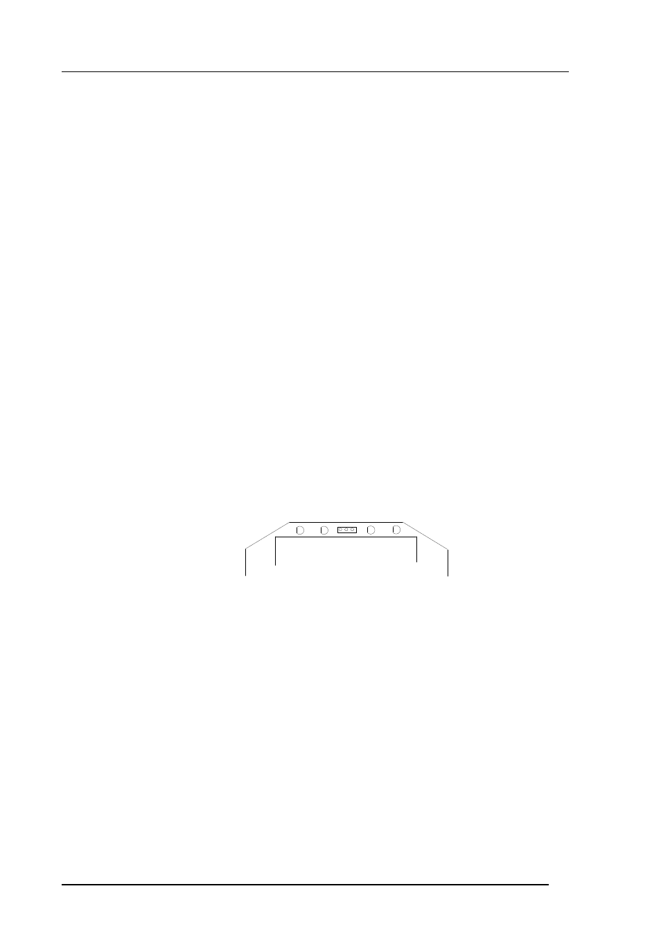
have been changed, they must be changed back. Connect the RS 232C
port of the terminal to connector X17 on the top of the main board
and switch the power on.
RX GND TX
X17
Single loop wiring
•
Set the address of the transmitter; it can be any number between 1 and
99. In this example the address is 22:
>addr 22
Address : 22
•
Set the serial bus settings according to your network specifications.
This setting will become valid after next RESET or power off:
>seri 2400 e 7 1 h
2400 E 7 1 HDX