Installation, R3 r6 – Vaisala HMP228 User Manual
Page 84
HMP228
Appendix 4: RS 485/422 serial port module
M210282en-A
78
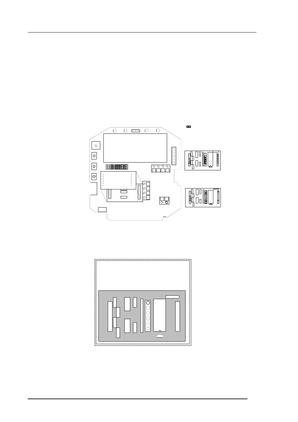
1. INSTALLATION
Switch the transmitter off.
Resistors R2, R3 and R4 between connectors X4 and X5 in the component
board in the cover of the transmitter are removed with side-cutting pliers. The
module is plugged in connectors X4 and X5 on the main board of the HMP228
transmitter; connector X1 on the module board to connector X4 and connector
X2 to connector X5.
X1
X2
+ -
C
h1
Ch2
-
- +
+
R2
R3
R4
X6
RX HI
RX LO
TX LO
TX HI
X4
X5
RX
TX
X1
X2
H
I
H
I
LO
L
O
X1
X2
R3
R6
Jumper ( ) selections for the
RS 485/422 serial bus module
Single pair
Dual pair
serial bus
module
Cut off the resistors R2, R3 and R4 on the main board.
New signal names for X6 screw terminal are on the module.
Follow the instructions on the module:
X1 to X4 and
X2 to X5 on the mother board
NOTE! If the transmitter is NOT at the end
of the bus OR the line has a dynamic line
termination, the resistors R3 and R6 have
to be removed!
RX GND TX
24V
RS 485/422
Connect the data wires to screw terminal X6 on the main board. Switch the
power on.