Vaisala HMP228 User Manual
Page 37
HMP228
M210282en-A
Operating Manual
31
T = D0 +R x {D1 + R x [D2 + R x (D3 + R x D4)]}
where
D0
=
-243.5673014
D1
=
2.278542701
D2
=
0.002050681
D3
=
-6.15025E-06
D4
=
1.34949E-08
4.7
Analogue output channels
4.7.1
Setting the analogue outputs
The HMP228 transmitters can be ordered with the required current or voltage
outputs already selected. If the outputs need to be changed, move the jumpers
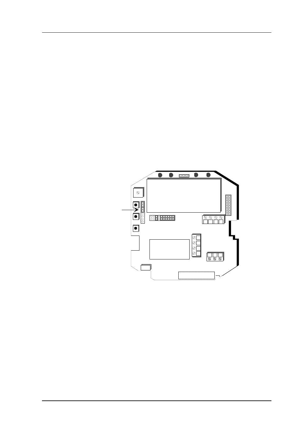
in connector X15 into positions as shown in Figure 4.7.1.2.
24V
Sensor connections
Current loop or
RS485 module
Ch1 Ch2
+ -
nc
Tx
GND
Rx
-
- +
+
X55
Spare
jumpers
Figure 4.7.1.1
Spare jumpers
See also other documents in the category Vaisala Humidifiers:
- Calibration of Digital Transmitters with HMI41 (36 pages)
- Calibration of Series HMDW2030 and HMP130 Transmitter with HMI41 (14 pages)
- Calibration of Series HMDW6070 and HMP140 Transmitter with HMI41 (30 pages)
- HM34 (30 pages)
- HM40 (47 pages)
- HM44 (52 pages)
- HM70 (83 pages)
- HMD40 (1 page)
- HMD60 (4 pages)
- HMD70 (18 pages)
- HMDW110 (62 pages)
- HMDW80 (51 pages)
- HMI41 (74 pages)
- HMP41 (72 pages)
- HMK15 (39 pages)
- HMM100 (71 pages)
- HMM105 (23 pages)
- HMM211 (42 pages)
- HMM212 (36 pages)
- HMM213 (52 pages)
- HMP140 (28 pages)
- HMP155 (84 pages)
- HMP230 (163 pages)
- HMP240 (130 pages)
- HMP260 (118 pages)
- HMP60 (71 pages)
- HMT100 (52 pages)
- HMT120 (87 pages)
- HMT130 (95 pages)
- HMT140 (76 pages)
- HMT310 (88 pages)
- HMT310 (105 pages)
- HMT330 (209 pages)
- HMT360 (97 pages)
- HMT360 (63 pages)
- HMT360N (110 pages)
- HMW40 (1 page)
- HMW90 (110 pages)
- SHM40 (68 pages)
- RDP100 (14 pages)