Vaisala HMP228 User Manual
Page 42
HMP228
Operating Manual
M210282en-A
36
24V
Sensor connections
Current loop or
RS485 module
Ch1 Ch2
+ -
nc
Tx
GND
Rx
-
- +
+
X15
Ch1
Ch2
+
+
-
-
X2
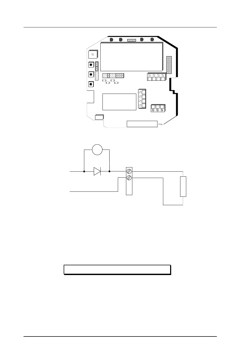
Figure 4.8.1.1
Location of the CH1 and CH2 test points
CH1+
CH1-
TEST POINTS
CH1+
CH1-
mA
R
L
X2
Figure 4.8.1.2 Circuit diagram of the analogue output current test
points.
4.8.1
Calibration of the analogue outputs
The analogue outputs have been calibrated at the factory and since they are
very stable, calibration of the outputs should be performed only when there is
reason to believe that their adjustments have changed.
Disconnect the security lock jumper!
See also other documents in the category Vaisala Humidifiers:
- Calibration of Digital Transmitters with HMI41 (36 pages)
- Calibration of Series HMDW2030 and HMP130 Transmitter with HMI41 (14 pages)
- Calibration of Series HMDW6070 and HMP140 Transmitter with HMI41 (30 pages)
- HM34 (30 pages)
- HM40 (47 pages)
- HM44 (52 pages)
- HM70 (83 pages)
- HMD40 (1 page)
- HMD60 (4 pages)
- HMD70 (18 pages)
- HMDW110 (62 pages)
- HMDW80 (51 pages)
- HMI41 (74 pages)
- HMP41 (72 pages)
- HMK15 (39 pages)
- HMM100 (71 pages)
- HMM105 (23 pages)
- HMM211 (42 pages)
- HMM212 (36 pages)
- HMM213 (52 pages)
- HMP140 (28 pages)
- HMP155 (84 pages)
- HMP230 (163 pages)
- HMP240 (130 pages)
- HMP260 (118 pages)
- HMP60 (71 pages)
- HMT100 (52 pages)
- HMT120 (87 pages)
- HMT130 (95 pages)
- HMT140 (76 pages)
- HMT310 (88 pages)
- HMT310 (105 pages)
- HMT330 (209 pages)
- HMT360 (97 pages)
- HMT360 (63 pages)
- HMT360N (110 pages)
- HMW40 (1 page)
- HMW90 (110 pages)
- SHM40 (68 pages)
- RDP100 (14 pages)