Figure 2.3.1 electrical connections – Vaisala HMP228 User Manual
Page 16
HMP228
Operating Manual
M210282en-A
10
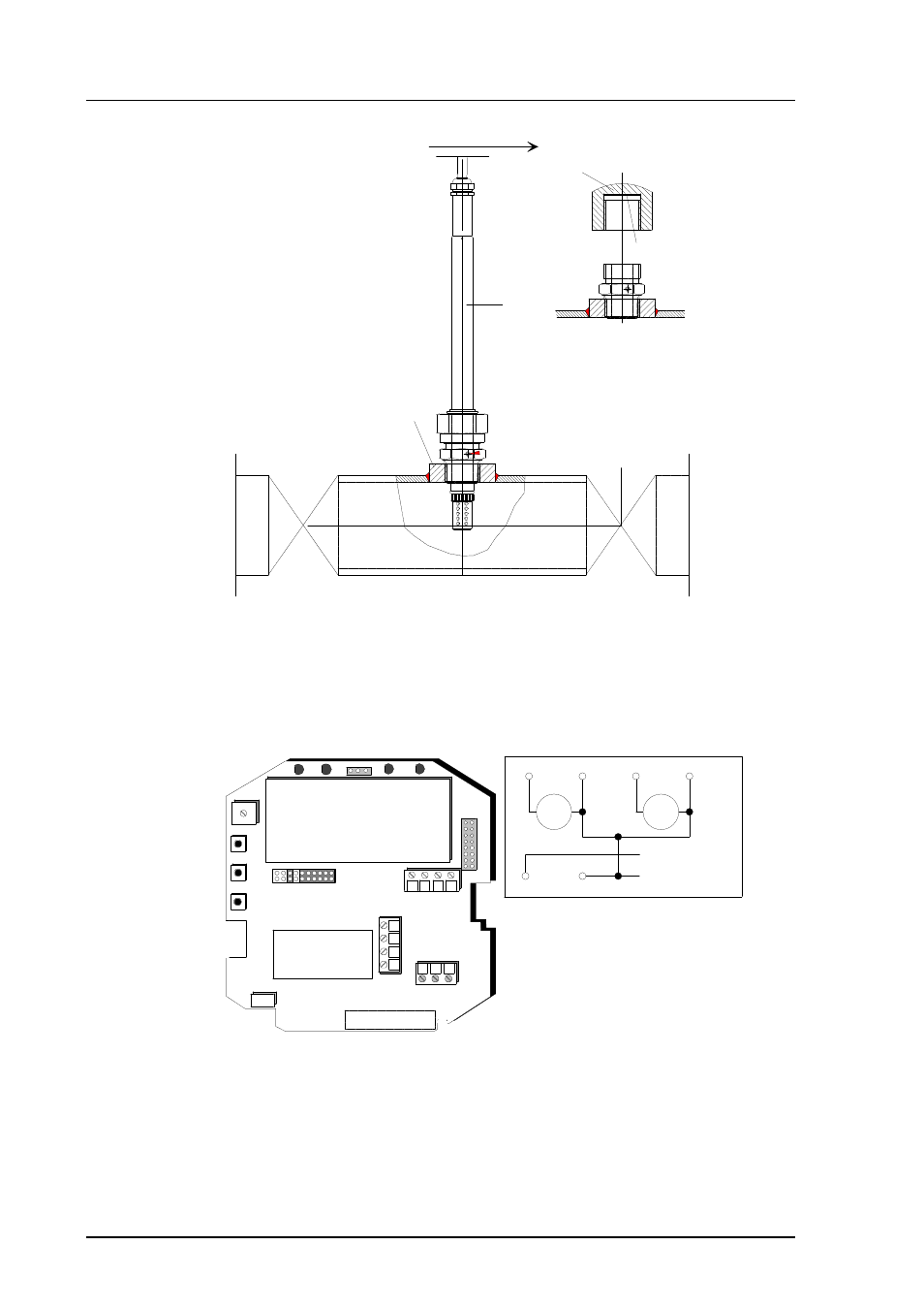
when the probe is pulled
out for maintenance, cap
the hole with a capped nut;
this way, the process can
be open although the probe
is not in place
capped nut
DIN 917-M22x1.5
sealing
closing valve
(ball valve)
welded sleeve
(G1/2) or tube
with thick walls
probe
Figure 2.2.4
Installing the sensor head directly in a process pipe
2.3
Signal cabling and grounding
2.3.1
Electrical connections
CH1- and CH2- are connected
together internally (X2).
DO NOT USE POWER SUPPLY
GROUND (-) AS OUTPUT
SIGNAL GROUND (X1)!
24V
Sensor connections
Current loop or
RS485 module
Ch1 Ch2
+ -
nc
Tx
GND
Rx
-
- +
+
X1
X2
+ Ch1 -
+ Ch2 -
+ 24V -
Power supply
V
mA
V
mA
Figure 2.3.1
Electrical connections
See also other documents in the category Vaisala Humidifiers:
- Calibration of Digital Transmitters with HMI41 (36 pages)
- Calibration of Series HMDW2030 and HMP130 Transmitter with HMI41 (14 pages)
- Calibration of Series HMDW6070 and HMP140 Transmitter with HMI41 (30 pages)
- HM34 (30 pages)
- HM40 (47 pages)
- HM44 (52 pages)
- HM70 (83 pages)
- HMD40 (1 page)
- HMD60 (4 pages)
- HMD70 (18 pages)
- HMDW110 (62 pages)
- HMDW80 (51 pages)
- HMI41 (74 pages)
- HMP41 (72 pages)
- HMK15 (39 pages)
- HMM100 (71 pages)
- HMM105 (23 pages)
- HMM211 (42 pages)
- HMM212 (36 pages)
- HMM213 (52 pages)
- HMP140 (28 pages)
- HMP155 (84 pages)
- HMP230 (163 pages)
- HMP240 (130 pages)
- HMP260 (118 pages)
- HMP60 (71 pages)
- HMT100 (52 pages)
- HMT120 (87 pages)
- HMT130 (95 pages)
- HMT140 (76 pages)
- HMT310 (88 pages)
- HMT310 (105 pages)
- HMT330 (209 pages)
- HMT360 (97 pages)
- HMT360 (63 pages)
- HMT360N (110 pages)
- HMW40 (1 page)
- HMW90 (110 pages)
- SHM40 (68 pages)
- RDP100 (14 pages)