Installation – Vaisala HMP228 User Manual
Page 95
HMP228
M210282en-A
Appendix 5: Digital current loop module
89
1.
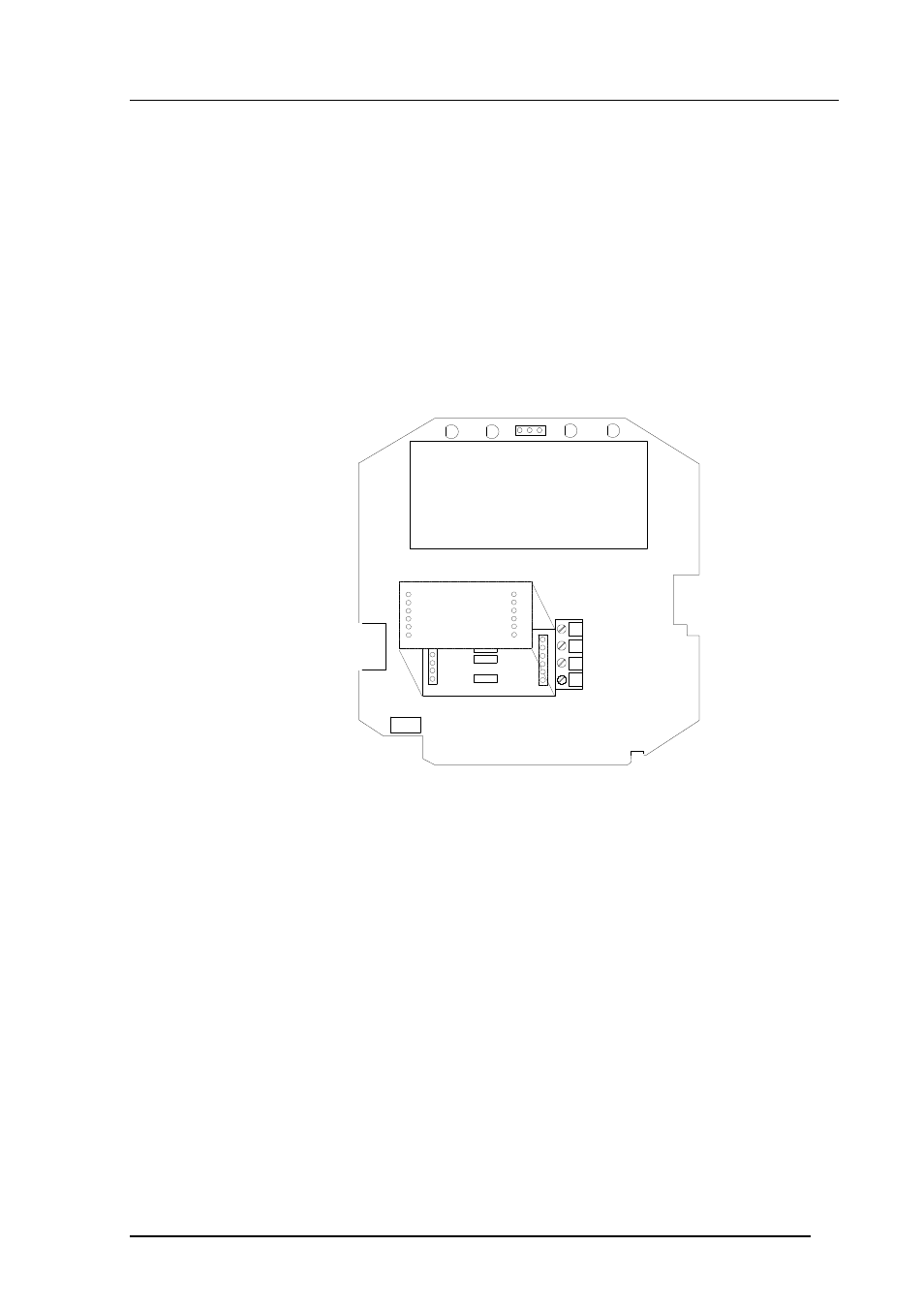
INSTALLATION
Switch the transmitter off.
Resistors R2, R3 and R4 between connectors X4 and X5 in the component
board in the cover of the transmitter are removed with side-cutting pliers. The
module is plugged in connectors X4 and X5 on the main board of the HMP228
transmitter; connector X1 on the module board to connector X4 and connector
X2 to connector X5.
RX GND TX
R2
R3
R4
X6
RX +
TX +
X4
X5
Current loop
module
X1
X2
D
A
T
A
L
O
O
P
S
TX -
RX -
X17
Connect the data wires to screw terminal X6 on the main board. Switch the
power on.
See also other documents in the category Vaisala Humidifiers:
- Calibration of Digital Transmitters with HMI41 (36 pages)
- Calibration of Series HMDW2030 and HMP130 Transmitter with HMI41 (14 pages)
- Calibration of Series HMDW6070 and HMP140 Transmitter with HMI41 (30 pages)
- HM34 (30 pages)
- HM40 (47 pages)
- HM44 (52 pages)
- HM70 (83 pages)
- HMD40 (1 page)
- HMD60 (4 pages)
- HMD70 (18 pages)
- HMDW110 (62 pages)
- HMDW80 (51 pages)
- HMI41 (74 pages)
- HMP41 (72 pages)
- HMK15 (39 pages)
- HMM100 (71 pages)
- HMM105 (23 pages)
- HMM211 (42 pages)
- HMM212 (36 pages)
- HMM213 (52 pages)
- HMP140 (28 pages)
- HMP155 (84 pages)
- HMP230 (163 pages)
- HMP240 (130 pages)
- HMP260 (118 pages)
- HMP60 (71 pages)
- HMT100 (52 pages)
- HMT120 (87 pages)
- HMT130 (95 pages)
- HMT140 (76 pages)
- HMT310 (88 pages)
- HMT310 (105 pages)
- HMT330 (209 pages)
- HMT360 (97 pages)
- HMT360 (63 pages)
- HMT360N (110 pages)
- HMW40 (1 page)
- HMW90 (110 pages)
- SHM40 (68 pages)
- RDP100 (14 pages)