Vaisala HMP228 User Manual
Page 38
HMP228
Operating Manual
M210282en-A
32
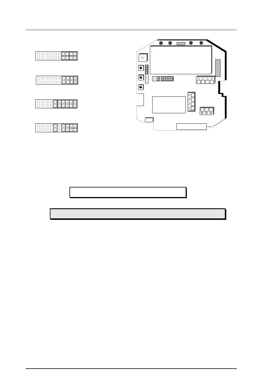
24V
Sensor connections
Current loop or
RS485 module
Ch1 Ch2
+ -
nc
Tx
GND
Rx
-
- +
+
X15
Ch1Ch2
C
h
1
C
h
2
Ch1Ch2
C
h
1
C
h
2
Ch1Ch2
C
h
1
C
h
2
Ch1Ch2
C
h
1
C
h
2
Current outputs
0... 20/4... 20 mA
Voltage outputs
0... 5/0... 10 V
Voltage outputs
0... 1 V
Ch1 0... 1 voltage ouput
Ch 2 current output
Figure 4.7.1.2
Selecting the analogue outputs with jumpers
All jumpers are used only with the 0...1 V outputs. When other outputs are in
use, the spare jumpers are kept in connector X55.
4.7.1.1
Using serial output
Disconnect the security lock jumper!
AMODE a bb.bbb cc.ccc d ee.eee ff.fff
a
= channel 1:
U = voltage output
I = current output
bb.bbb
= lower limit of channel 1
cc.ccc
= upper limit of channel 1
d
= channel 2:
U = voltage output
I = current output
ee.eee
= lower limit of channel 2
ff.fff
= upper limit of channel 2
The bb.bbb, cc.ccc, ee.eee and ff.fff parameters are entered in volts or
milliamperes.
Example: lower limit of channel 1 is 0 V and upper limit 1 V (U 0 1)
lower limit of channel 2 is 2 V and upper limit 10 V (U 2 10)
>AMODE U 0 1 U 2 10
Ch1 : 0.000 ... 1.000 V
Ch2 : 2.000 ... 10.000 V