Troubleshooting, Analog output error notification, Chapter 6 – Vaisala HMM100 User Manual
Page 63: Table 8, Error levels for analog output modes
Chapter 6 ____________________________________________________________ Troubleshooting
VAISALA ________________________________________________________________________ 61
CHAPTER 6
TROUBLESHOOTING
This chapter describes the analog output error notification behavior,
some common problems, their probable causes and remedies, and
provides contact information for technical support.
Analog Output Error Notification
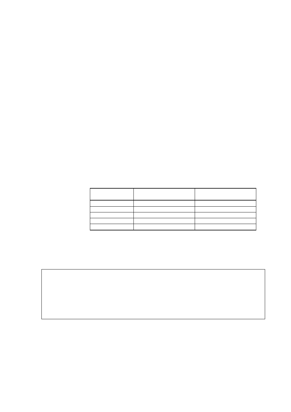
If the module is unable to measure due to an error, the analog output will
be set to an error level. The error level depends on the currently selected
analog output mode; see Table 8 below.
Table 8
Error Levels for Analog Output Modes
Analog Output
Mode
Default Error Level
Maximum Value
0 ... 1 V
0 V
2 V
0 ... 5 V
0 V
6 V
0 ... 10 V
0 V
12 V
0 ... 20 mA
0 mA
30 mA
4 ... 20 mA
3.8 mA
30 mA
You can check the current status of the analog output via the serial
interface by using the STATUS command. You can also disable this
error notification behavior; see section Show Calibration Info on page 32.
NOTE
If the error state voltage exceeds the normal output range, the minimum
required supply voltage is higher. As a rule, add one volt to the supply
voltage to get one additional volt from the signal. See Table 10 on page
66.
For example, for a 0 … 5 V output, a 6 V error state needs an 11 V
supply voltage.