2 encoder connections, 1 terminal blocks, 1 terminal blocks sk 53xe size 1 – NORD Drivesystems BU0510 User Manual
Page 8: Terminal blocks sk 53xe size 1 – 4
POSICON position control for NORD frequency inverters, SK 530E and above
8
Subject to technical alterations
BU 0510 GB-3911
2 Encoder connections
The internal zero point of the inverter can be adjusted by specifying an offset value.
A possible reduction ratio between the position measurement system (encoder) and the motor can be taken
into account by the use of transformation and reduction ratios. The motor and the position measurement
system (encoder) do not need to have the same direction of rotation. A negative ratio must be set if the
direction of rotation is different.
2.1 Terminal blocks
The terminal blocks for the control connections and for the encoder differ between the versions and sizes of
the frequency inverter.
2.1.1
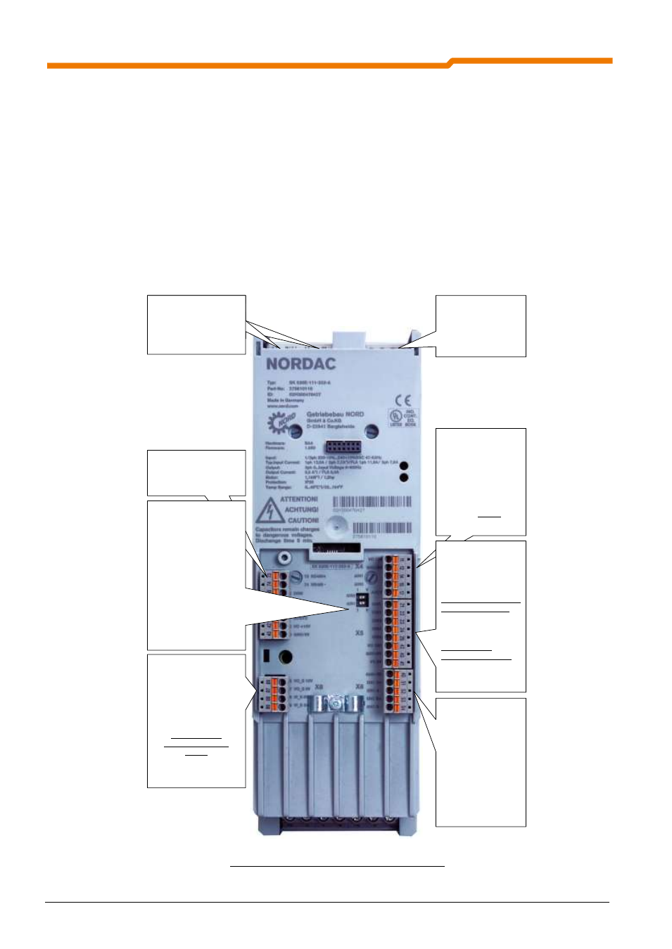
Terminal blocks SK 53xE Size 1
– 4
X6:
Incremental
encoder input
Encoder, e.g.: TTL,
10-30V, RS422,
2048
impulses/rotation
Note:
5V encoders should
not be used.
X7:
additional digital
inputs and outputs
DIP switch:
Switching from analog
inputs AIN2/AIN1
current/voltage
setpoint
I = current 0/4...20mA
V = voltage 0...10V
NOTE:
AIN2
– upper DIP
Switch
AIN1
– lower DIP
Switch
X8:
VI_S 24V, pulse block
input
VO_S 15/24V, output
for commissioning
without safety
switching device
only for SK 53xE
and not with 115VAC
devices
further details in
handbook BU 0530
X4:
analog inputs and
outputs
+10V max. 5mA
0...10V or
0/4...20mA
Analog output
: 0 …
10V
X5: digital inputs and
voltage supply
R
i DIN
approx. 4.5k
with SK 530E
Terminal 42internal
+15V max. 150mA
+5V max. 250mA
with SK 535E
Terminal 44external
+18-30V min. 800mA
X11:
1x RJ12 socket to
connect the RS232 or
RS485 interface
X9/X10:
2x RJ45 socket to
connect the
CAN/CANopen
interface
X9
X10
X11
Fig. 1: Terminal blocks, SK 53xE Size 1 - 4