Dig i n 5, Vo + 5 v – NORD Drivesystems BU0510 User Manual
Page 19
2 Encoder connection
BU 0510 GB-3911
Subject to technical alterations
19
2.3.3
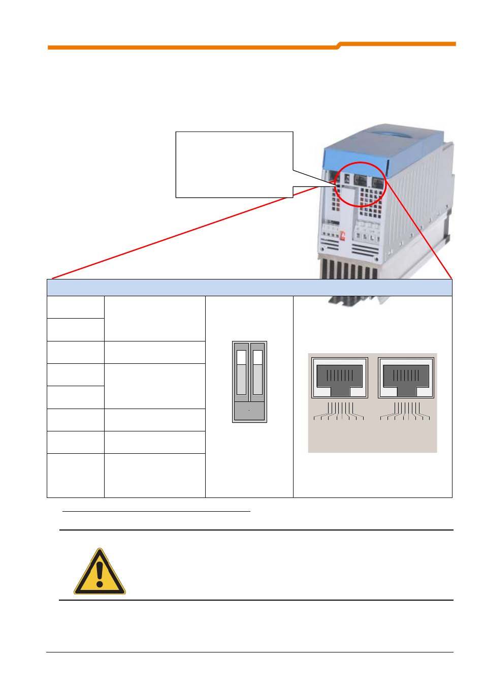
Assignment of the CAN interface on the frequency inverter
The 24V supply for the absolute encoder and the CAN Bus/CANopen interface must be provided via an
external supply. For the assignment of the terminals, please refer to the encoder manufacturer´s operating
instructions.
Table 11: Contact assignment for the RJ45 interface
NOTE
Recommendation: To provide strain relief, the CAN cable can be connected to the screening
angle of the EMC Kit (option). Details of the EMC Kit can be found in the BU0500 manual.
DIP switch and 2xRJ45 terminal block, CAN Bus (SK 520E/530E only)
1
CAN_H
CAN Bus signal
max. baud rate
...500kBaud
1 2
ON
DIP switch 2
for CAN Bus
termination resistor
R=120
V
R
E
F
1
0
V
A
G
N
D
0
V
A
IN
1
+
A
IN
2
+
A
O
U
T
1
D
IG
I
N
1
D
IG
I
N
2
D
IG
I
N
3
D
IG
I
N
4
V
O
+
1
5
V
D
G
N
D
0
V
11
12
13
14
16
22
23
24
25
42
40
21
D
IG
I
N
5
1
2
3
4
R
E
L
2
.2
R
E
L
2
.1
R
E
L
1
.2
R
E
L
1
.1
C
A
N
_H
C
A
N
_L
C
A
N
_G
N
D
nc
C
A
N
_S
H
L
D
C
A
N
_G
N
D
nc
C
A
N
_2
4
V
C
A
N
_H
C
A
N
_L
C
A
N
_G
N
D
nc
C
A
N
_S
H
L
D
C
A
N
_G
N
D
nc
C
A
N
_2
4
V
R
S
4
8
5
_A
R
S
4
8
5
_B
G
N
D
TX
D
R
X
D
41
V
O
+
5
V
+
5
V
RJ45: Pin No. 1 … 8
2
CAN_L
3
CAN_GND CAN-Bus GND
4
nc
No function
5
nc
6
CAN_SHD Cable shield
7
CAN_GND GND / 0V
8
CAN_24V
External 24VDC +/- 25%
voltage supply
(Load capacity at least
30mA)
For SK 520E/530E:
CANbus oder CANopen
über
RJ45
Buchsen,
Abschlusswiderstand
ist zuschaltbar
SK 520E or higher:
CAN interface, two RJ45
sockets, the bus
termination resistor can
be switched in.