NORD Drivesystems BU0510 User Manual
Page 41
BU 0510 GB-3911
Subject to technical alterations
41
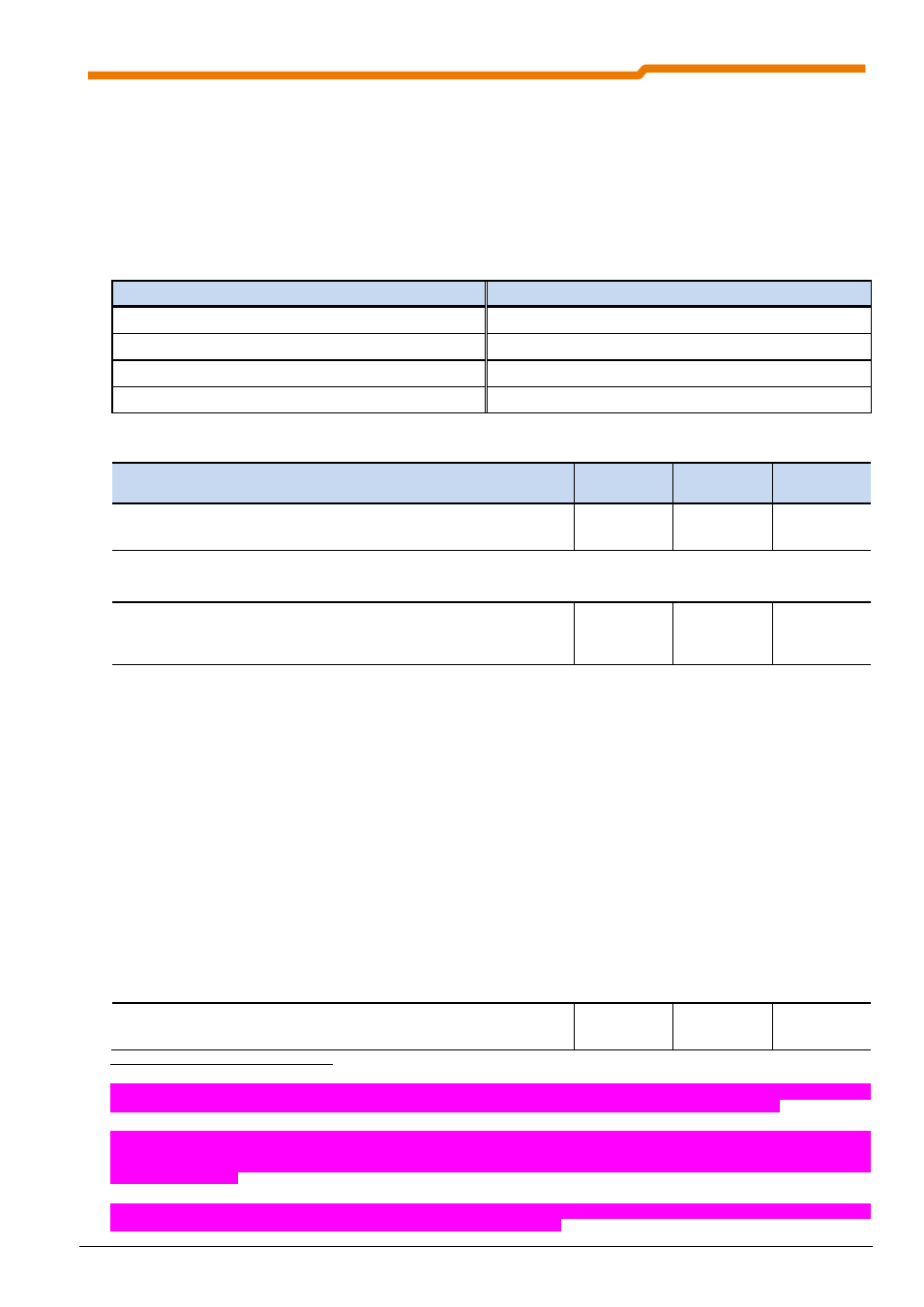
List of possible digital functions for the analog outputs P418
(only POSICON functions)
All relay functions described in Parameter >Function Relay 1< P434 can also be transferred via the analog
output. If a condition has been fulfilled, then there will be 10V at the output terminals. Negation of the function
can be set in parameter >Analog output standardisation< P419.
Value
Function
Value
Function
34
Reference point
38
Position array value
35
Position reached
39
Comparative position reached
36
Comparative position
40
Comparative position value reached
37
Comparative position value
Parameter
{factory setting}
Setting value / Description / Note
Device
Supervisor
Parameter
set
P420
Digital input 1
(Digital input 1)
up to SK
535E
0 ... 74
{ 1 }
Enable right as factory setting, control terminal 21 (DIN1)
Various functions can be programmed. These can be seen in the following table.
P420
[-01]
...
[-10]
Digit inputs
(Digital inputs)
SK 540E and
above
0 ... 80
{ [-01] = 1 }
{ [-02] = 2 }
{ [-03] = 8 }
{ [-04] = 4 }
all others { 0 }
Up to 10 inputs which can be freely programmed with digital functions are available in the SK
54xE. Of these inputs, analog inputs 1 and 2 of the frequency inverter do not comply with
EN61131-2 (Type 1 digital inputs).
[-01] = Digital input 1 (DIN1): Enable right, (default),
Terminal 21
[-02] = Digital input 2 (DIN2): Enable left, (default),
Terminal 22
[-03] = Digital input 3 (DIN3): Parameter switching, (default),
Terminal 23
[-04] = Digital input 4 (DIN4): Fixed frequency 1 (P429), (default),
Terminal 24
[-05] = Digital input 5 (DIN5): No function, (default),
Terminal 25
4
[-06] = Digital input 6 (DIN6): No function, (default),
Terminal 26
[-07] = Digital input 7 (DIN7): No function, (default),
Terminal 27
5
[-08] = Digital function Analog1 (AIN1), "Digital function of analog input 1": Terminal 14
6
[-09] = Digital function Analog2 (AIN2), "Digital function of analog input 2": Terminal 16
c
[-10] = Digital input 8 (DIN8): No function, (default),
Terminal 7
b
P421
Digital input 2
(Digital input 2)
up to SK
535E
4
Up to and including Size 4, digital input 5 is not available. In place of this a potential-free isolated thermistor input is implemented, whose function cannot be
disabled. If no thermistor is present the two terminals TF- and TF+ must be bridged. Parameterisation of this input does not have any effect.
5
Digital input 7 (DIN7) can also be used as digital output 3 (DOUT3 / Binary output 5). It is recommended that either an input function (P420 [-07] or an output
function (P434 [-05]) is parameterised. However, if and input function and an output function are parameterised, a High signal from the output function will
result in the activation of the input function. This IO-exclusion is hence used as a kind of "flag". This also applies for digital input 8 (DIN8) and digital output 2
(DOUT2 / binary output 4).
6
The analog inputs 1 and 2 (AIN1 / 2) can also process digital functions. Care must be taken that either an analog function (P400 [-01]/[-02]) or a digital
function (P420 [-08]/[-09]) is parameterised in order to prevent misinterpretation of the signals.