A)normal path b) optimised path – NORD Drivesystems BU0510 User Manual
Page 29
3 Description of function
BU 0510 GB-3911
Subject to technical alterations
29
3.2.4.2
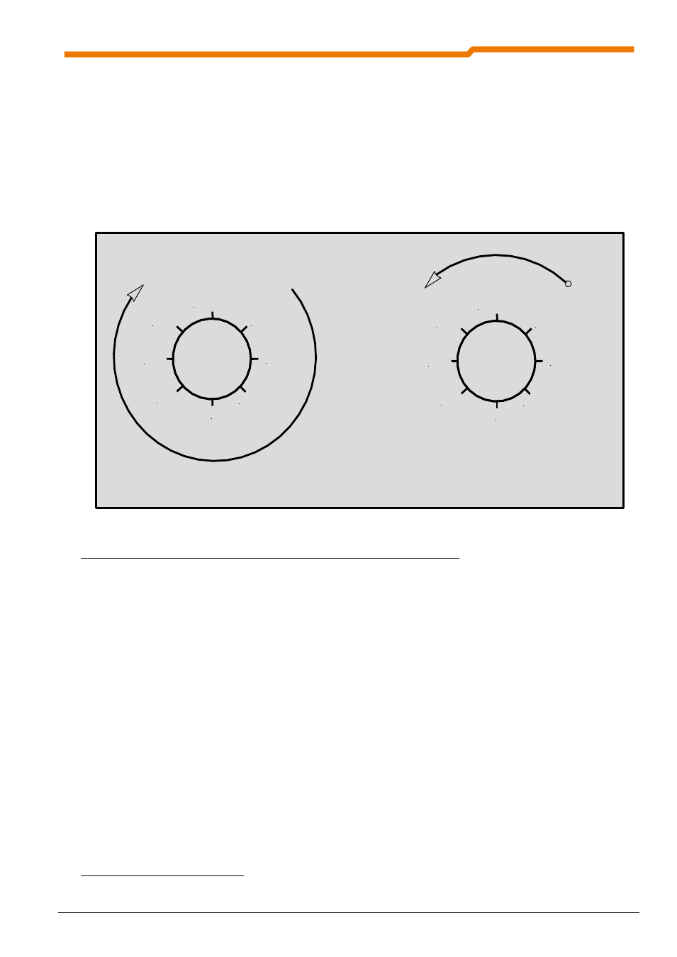
Optimised path positioning with arbitrary rotation of the encoder
If more than one rotation of the encoder is required for the entire travel path, the overflow point
3
must be
determined. This results from half of the entire travel path. This value must be entered in parameter P615
"Maximum Position". Here it should be noted that the precision of the value may have a maximum of three
decimal places. A deviant error causes an additional error with each overflow.
NOTE:
If an addition of the errors is to be avoided, the system must be referenced again after each
rotation.
-37.875
37.875
-12.625
12.625
0
50.5 / -50.5
-25.25
25.25
-37.875
37.875
-12.625
12.625
0
50.5 / -50.5
-25.25
25.25
a)normal path
b) optimised path
Fig. 7: Standard a) and optimised b) movement with a multi-turn application
Example: The total travel path is 101 rotations of the encoder, then the "Maximum Position" in
P615 = 0.5 * 101 rotations = 50.5 rotations must be entered.
The above example is for a speed ratio or reduction ratio of "1". The maximum value of the position or the
overflow point is calculated as follows:
n
max
:
Maximum value of motor rotation
n
max
= 0.5 * U
D
* Ü
b
/ U
n
Ü
b
:
Speed Ratio (P607[-01])
U
n
:
Reduction Ratio (P608[-01])
U
D
Rotations of rotary encoder
Example: The incremental encoder is installed on the output side of the gear unit. The gear unit has a ratio of
i = 26.3.
n
max
=0.5 * 101 rotations * 263 / 10 = 1328.15 rotations.
3
The overflow point corresponds to 1/2 of an encoder revolution