NORD Drivesystems BU0510 User Manual
Page 42
POSICON position control for NORD frequency inverters, SK 530E and above
42
Subject to technical alterations
BU 0510 GB-3911
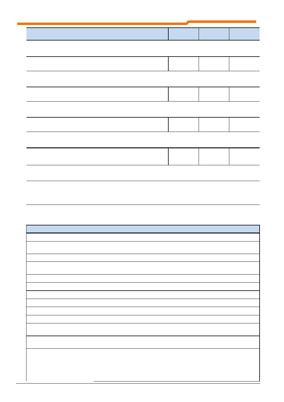
Parameter
{factory setting}
Setting value / Description / Note
Device
Supervisor
Parameter
set
0 ... 74
{ 2 }
Enable left as factory setting, control terminal 22 (DIN2)
Various functions can be programmed. These can be seen in the following table.
P422
Digital input 3
(Digital input 3)
up to SK
535E
0 ... 74
{ 8 }
Parameter set switching Bit 0 as factory setting, control terminal 23 (DIN3)
Various functions can be programmed. These can be seen in the following table.
P423
Digital input 4
(Digital input 4)
up to SK
535E
0 ... 74
{ 4 }
Fixed frequency 1 (P429) as factory setting, control terminal 24 (DIN4)
Various functions can be programmed. These can be taken from the following table.
P424
Digital input 5
(Digital input 5)
up to SK
535E
0 ... 74
{ 0 }
No function as factory setting, control terminal 25 (DIN5)
Various functions can be programmed. These can be seen in the following table.
P425
Digital input 6
(Digital input 6)
From SK
520E
to SK 535E
0 ... 74
{ 0 }
No function as factory setting, control terminal 26 (DIN6)
Various functions can be programmed. These can be seen in the following table.
(SK 520/53xE) Function of digital input 7 = P470 , Control terminal 27 (DIN7)
For a description of functions, see the following table(s).
List of the possible functions of digital inputs P420 ... P425, P470
(only POSICON functions)
Value Function
Description
Signal
22
Approach reference point Start of reference point run (see Section 3.2.1.1)
High
23
Reference point
Reference point reached (see Section 3.2.1.1)
10
Flank
24
Teach
– In
Start of Teach-in function (see Section 3.4)
High
25
Quit Teach
– In
Save actual position (see Section 3.4)
01
Flank
55
Bit 0 PosArr / Inc
Bit 0 position array / position increment array (see Section 3.3)
High
56
Bit 1 PosArr / Inc
Bit 1 position array / position increment array (see Section 3.3)
High
57
Bit 2 PosArr / Inc
Bit 2 position array / position increment array (see Section 3.3)
High
58
Bit 3 PosArr / Inc
Bit 3 position array / position increment array (see Section 3.3)
High
59
Bit 4 PosArr / Inc
Bit 4 position array / position increment array (see Section 3.3)
High
60
Bit 5 PosArr / Inc
Bit 5 position array / position increment array (see Section 3.3)
High
61
Reset position
Reset actual position (see Section 3.2.1.2)
01
Flank
62
Sync. position array
Adoptation of a preselected position (see Section 3.3.1 )
01
Flank
63
Synchronous operation
OFF
With function P610 = 2 "Synchronous operation", synchronous
operation is interrupted, however the drive unit remains in position
control mode. With the 0
1
flank the position setpoint (P602) from the master drive is reset and the
drive unit returns to position "0" or to the position saved in the position
offset (P609) and remains there.
High