3 hiperface encoders – NORD Drivesystems BU0510 User Manual
Page 14
POSICON position control for NORD frequency inverters, SK 530E and above
14
Subject to technical alterations
BU 0510 GB-3911
2.2.3
Hiperface encoders
(SK 540E and above)
Hiperface is a mixture of incremental encoder and absolute encoder and combines the advantages of both
encoder types. The absolute value is initially only formed when the device is switched on and is
communicated by the RS485 specification bus parameter interface to the external counter in the controller,
which then continues counting incrementally from this absolute value using the analog sine/cosine signal.
During operation the counted position is continuously compared with the measured absolute position of the
encoder.
Hiperface encoders are suitable for positioning in combination with servo mode.
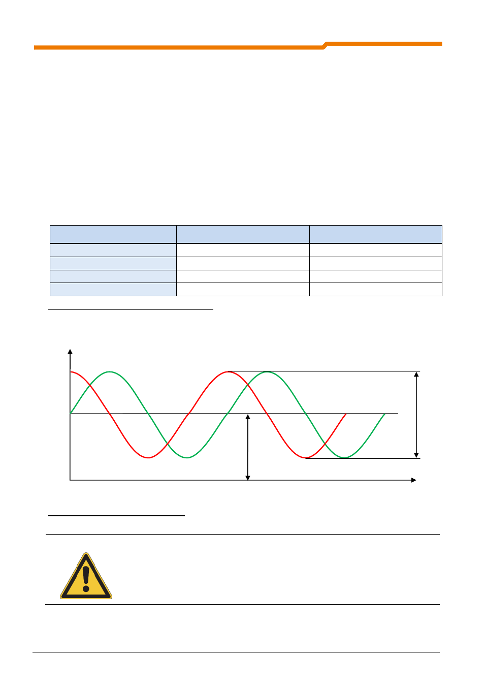
The requirements for the analog signal are shown in the following table. It must be noted that the tolerances
in the voltages affect the precision of the determined position.
The supply voltage for the encoder is 7-12V. An external source or the internal 12V voltage can be used as
the voltage supply.
Function
Signal designation
Signal voltage
Sine reference voltage
Sin Ref
2,5V U
m
Cosine reference voltage
Cos Ref
2,5V U
m
Sine signal
Sin
1V U
ss
Cosine signal
Cos
1V U
ss
Table 4: Signal details for Hiperface encoders
Fig. 4: Signals for Hiperface encoders
NOTE
The voltage difference between the SIN and COS tracks can be measured with the aid of
parameter P709 [-09] and [-10]. If the Hiperface encoder is rotated, the voltage difference
should range between approx. -0.5V and 0.5V.
U
ss
U
m