2 rj12 diagnostic socket – NORD Drivesystems BU0280 User Manual
Page 33
3 Displays and diagnosis
BU 0280 GB
Subject to technical amendments
33
3.2 RJ12 Diagnostic socket
All participants which are coupled via a common system bus (field bus module / frequency inverter (up to 4
devices)) can be read out and edited/parameterised via an RJ12 diagnostic socket. Either the diagnostic
socket of the frequency inverter or those of the bus connection units can be used. This provides users with a
convenient facility to perform diagnosis and parameterisation from a central point, without having to access the
particular frequency inverter at its location.
Although the customer unit SK CU4-DEV does not have an RJ12 connection, it can be accessed from any
other subscriber (frequency inverter) on the same system bus.
Terminal/
Designation
Function
Data
Description / wiring suggestion
Parameter
Diagnostic access / RJ12, RS485/RS232
1 RS485
A
Data cable RS485
Baud rate 9600
…38400
baud
Termination resistor
R=120
must be set by the
customer at the final
subscriber.
RS
48
5_
A
RS
48
5_
B
GN
D
TX
D
RX
D
+5
V
+2
4
V
RJ12: Pin No. 1
… 6
1: RS485_A
2: RS485_B
3: GND
4: RS232_TxD
5: RS232_RxD
6: +24V
P502
…P513
2 RS485
B
3 GND
Reference potential
for Bus signals
0V digital
4 232
TXD
Data cable RS232
Baud rate 9600
…38400
baud
5 232
RXD
6 +24V
24V voltage supply
from FI
24V
20%
The bus speed of the diagnostic interface is 38400 baud. Communication is carried out according to the USS
protocol.
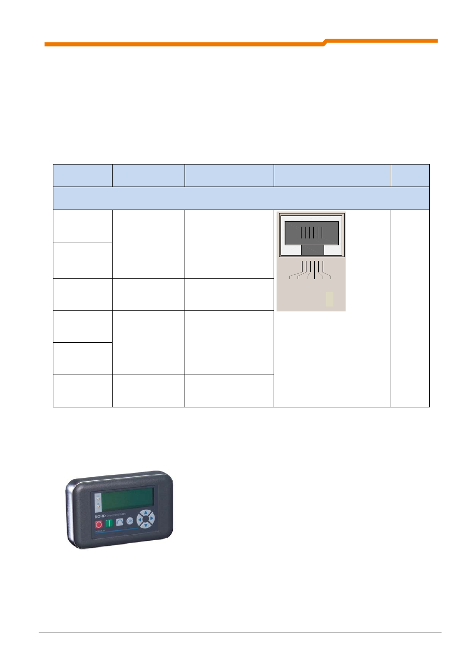
The ParameterBox SK PAR3H is available as a diagnostic tool.
The necessary connecting cables are included in the scope of
delivery of the ParameterBox. For a detailed description of use,
please refer to Manual BU0040.
ParameterBox SK PAR-3H