NORD Drivesystems BU0280 User Manual
Page 18
Supplementary Manual DeviceNet for NORDAC SK 200E
18
Subject to technical amendments
BU 0280 GB
2.1.3.3 Mounting the SK T14-TU-BUS on the SK 200E
The screw fittings and seals required for installation are enclosed with the modules or are fitted to the intended
locations.
Mounting
of the technology unit on the SK 200E
must be carried out as follows:
1. Switch off the mains.
2. Remove the two M25 caps on the required side
of the frequency inverter (right / left).
3. Remove the printed circuit board (with terminal
bar) from the BUS connection unit.
4. Install the SK TI4-TU-BUS (with adhered seal)
on the SK 200E using the 4 enclosed bolts.
5. Replace the printed circuit board (See point 3)
and carry out the electrical connections.
6. Fit and screw on the SK TU4 module.
2.1.3.4 Wall mounting the SK TI4-TU-BUS
The screw fittings (except for anchoring screws) and
seals required for installation are enclosed with the
modules or are fitted to the intended locations.
The connecting cable between the technology unit
and the SK 200E should not be longer than 30m.
1. Mount the SK TI4-TU-BUS connecting unit with
adhered seal on the wall-mounting kit. To do this:
Insert the 2 x cheese-head screws (enclosed
with wall-mounting kit) into the (countersunk)
holes from the outside and with the 2 x bolts
(enclosed with the wall-mounting kit) securely
screw both components together from the inside
(BUS connection unit).
2. Make a suitable cable connection between the technology unit and the frequency inverter. Take care that
there is appropriate screw fitting and sealing of the modules. The cable sets enclosed with the BUS
connection unit are not used.
3. Fit and screw on the SK TU4 module.
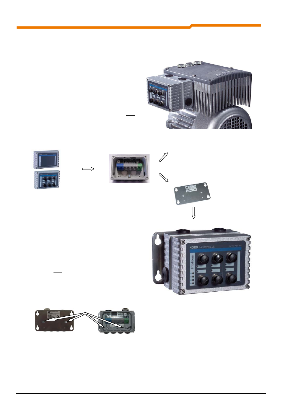
Technology unit SK TU4-DEV (-M12)
BUS connection unit SK TI4-TU-BUS
Mounting the external technology unit on the SK 200E
SK TI4-WMK-TU wall-mounting kit
Wall-mounting kit SK TI4 WMK TU with field bus technology unit