NORD Drivesystems BU0280 User Manual
Page 20
Supplementary Manual DeviceNet for NORDAC SK 200E
20
Subject to technical amendments
BU 0280 GB
2.2.2
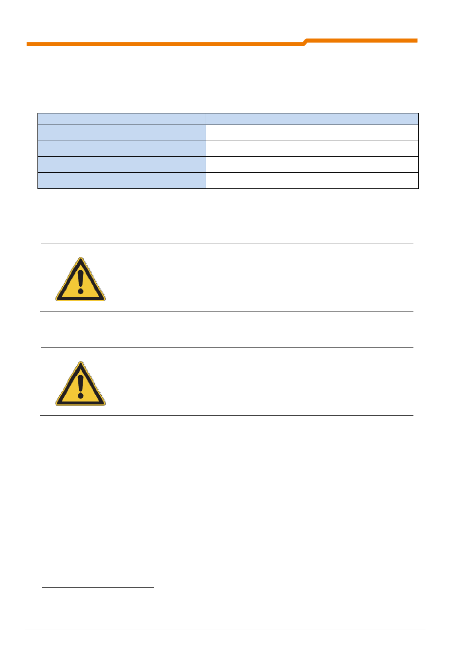
Control connections
The DeviceNet modules must be provided with one or two 24V DC (±20%, total current consumption 100mA)
control voltages. Wire end sleeves must be used for flexible cables.
Designation
Data
Rigid cable cross-section
0.14
… 2.5mm²
Flexible cable cross-section
0.14
… 1.5mm²
AWG standard
AWG 26-14
Tightening torque (for screw terminals)
0.5
…0.6Nm
Within the terminal box (unshielded cable section) the data cables (e.g. DeviceNet, system bus) must be
installed as short as possible and of equal length. Associated data cables (e.g.: Sys+ and Sys-) must be
twisted.
NOTE
In the customer unit, the DeviceNet is already installed with voltage isolation from the other
signal connections.
In case of EMC problems, voltage separation of the field bus supply, the digital inputs and
system bus interface and for the external technology unit also for the two additional digital
outputs should be provided.
NOTE
The cable shielding must be connected to the functional earthing
1
(usually the
electrically conducting mounting plate) in order to prevent EMC interference in the
device.
In order to achieve this, for DeviceNet connections it is mandatory that the metallic metric
EMC screws are used for the connection of the DeviceNet shielding lead to the frequency
inverter or the housing of the technology unit. This ensures a wide area connection of the
functional earthing
.
1
In systems, electrical equipment is usually connected to a functional earth. This serves as a means to dissipate leakage
and interference currents in order to ensure EMC characteristics and must therefore be implemented according to high
frequency technology aspects.