Ade interface, Figure 20: ade interface – Badger Meter M-Series M2000 User Manual
Page 52
ADE INTERFACE
This feature requires firmware version 1 10 or later Reference Badger Meter P/N 6734-003 to obtain a firmware upgrade kit
Enabling the meter as an ADE register requires three settings, all within the advanced menu, to be configured
•
Unit Multiplier – Selects the resolution of the display totalizer
•
Protocol Type – Selects the type of information to be transmitted to the ADE transmitter
•
Dial Type – Enables ADE and selects the number of significant totalizer digits to transmit
Changing the dial type from Disabled will automatically configure the necessary digital inputs/outputs It is not allowed to
manually change the digital inputs/outputs within the Input/Outputs menu
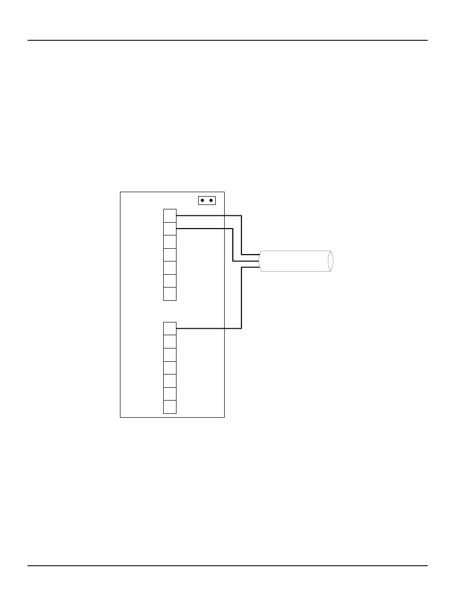
Below is a wiring diagram for connecting an ADE
transmitter to the meter
ADT Connections
1
2
3
4
5
6
7
8
9
10
11
12
13
14
IMPNROANOE: Remove jumper
JP1 before connecting transmitter
to meter
JP1
RED = CLOCK
GREEN = DATA
BLACK = GND
ADE Transmitter Cable
Output #1
COM
Input
Figure 20: ADE Interface
M-Series® M2000 Electromagnetic Flow Meter
Page 52
August 2012