Technical data – KROHNE OPTISWIRL 4070 EN User Manual
Page 72
8
TECHNICAL DATA
72
OPTISWIRL 4070
www.krohne.com
02/2013 - 4000150606 MA OPTISWIRL4070C R07 en
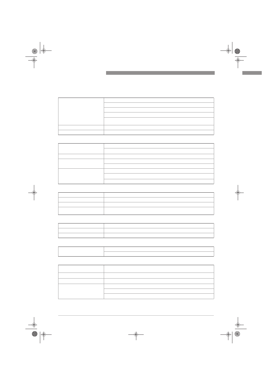
Installation conditions
Inlet run
≥ 20 x DN (without disturbing flow, after pipe narrowing, after a single 90° bend)
≥ 30 x DN (after a double bend 2x90°)
≥ 40 x DN (after a double three-dimensional bend 2x90°)
≥ 50 x DN (after control valves)
≥ 2 DN before flow straightener; ≥ 8 DN after flow straightener (specified values
apply only to original ≥ 20 DN inlet run)
Outlet run
≥ 5 x DN
Dimensions and weights
For detailed information refer to chapter "Dimensions and weights".
Materials
Measuring sensor and process
connections
Standard: 1.4404/316L
Option: Hastelloy
®
C-22 on request
Converter housing
Die-cast Aluminium
Pressure sensor gasket
Standard: FPM
Option: FFKM
Measuring tube gasket
Standard: 1.4435/316L
Option: Hastelloy
®
C-276
Selection depends on measuring sensor material/medium.
Process connections Flange version
DIN EN 1092-1
DN15...300 in PN16…100
ASME B16.5
½
...12" in 150…600 lb
JIS B 2220
DN15...300 in JIS 10…20 K
For detailed information on combination flange/pressure rating, refer to chapter
"Dimensions and weights".
Process connections Sandwich version
DIN
DN15...100 in PN100 (higher pressures on request)
ASME
½
...4" in 600 lb (higher pressures on request)
JIS
DN15...100 in 10…20 K (higher pressures on request)
Electrical connections
Power supply
Non-Ex: 14…36 VDC
Ex: 14…30 VDC
Current output
Description of the used
abbreviations
U
ext
= external voltage; R
L
= load + resistance
Measuring range
4...20 mA (max. 20.8 mA) + HART
®
protocol
Load
Minimum 0 Ω; maximum R
L
= ((U
ext
- 14 VDC) / 22 mA)
Error signal
Acc. to NAMUR NE43
Upper value: ≥ 21.0 mA
Lower value: ≤ 3.6 mA (not with HART
®
protocol)
MA_OPTISWIRL4070C_R07_en_150606_PRT.book Page 72 Wednesday, February 13, 2013 2:47 PM