Precautions before operation – GW Instek GRS-6000A Series User Manual
Page 7
GRS-6052A/6032A OSCILLOSCOPE
USER MANUAL
⎯ ⎯
8
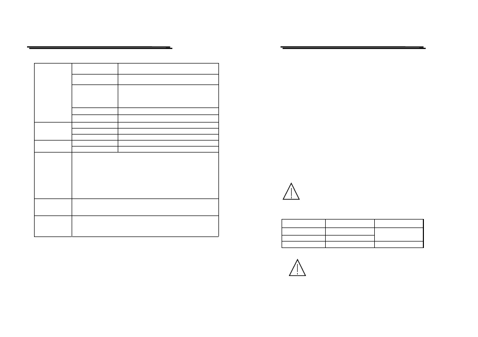
Panel Setting Display
CH1/CH2 sensitivity, sweep time, trigger
condition, digital storage function.
Panel Setting Save &
Recall
10 sets
Cursor Measurement
Cursor Measurement Function: ΔV, ΔT, 1/ΔT.
Cursor Resolution: 1/25 DIV.
Effective Cursor Range: Vertical:±3 DIV,
Horizontal: ±4 DIV
Text Readout Intensity Adjustable
CURSOR
READOUT &
CONTROL
INTERFACE
RS232 Interface
Remote control via a PC.
Voltage
AC100V, 120V, 230V ±10% selectable.
Frequency
50Hz or 60Hz.
LINE POWER
REQUIREMENT
Power Consumption
Approx. 70VA, 60W(max).
Dimensions
275(W)×130(H)×370(D) mm.
MECHANICAL
SPEC.
Weights
8.5 kg
OPERATING
ENVIRONMENT
Indoor use
Altitude up to 2000 m
Ambient temperature :
To satisfy specifications : 10℃ to 35℃ ( 50
° F to 95°F )
Maximum operating ranges: 0℃ to 40℃( 32
°F to 104°F )
Relative humidity: 85% RH(max.) non condensing
Installation Category : II
Pollution degree 2
STORAGE
TEMPERATUR
E & HUMIDITY
-10
° to 70℃, 70%RH(maximum)
ACCESSORIES
Power cord….............……….. 1
Instruction manual…………… 1
Probe (Ч1/Ч10)…………..….... 2
Measurement category I is for measurements performed on circuits not
directly connected to MAINS.
Measurement category II is for measurements performed on circuits
directly connected to the low voltage installation.
Measurement category III is for measurements performed in the building
installation.
Measurement category IV is for measurements performed at the source of
the low-voltage installation.
GRS-6052A/6032A OSCILLOSCOPE
USER MANUAL
⎯ ⎯
9
3.PRECAUTIONS BEFORE OPERATION
3-1.Unpacking the Oscilloscope
The product has been fully inspected and tested before shipping from the
factory. Upon receiving the instrument, please unpack and inspect it to check if
there is any damages caused during transportation. If any sign of damage is
found, notify the bearer and/or the dealer immediately.
3-2.Checking the Line Voltage
The oscilloscope can be applied any kind of line voltage shown in the table
below. Before connecting the power plug to an AC line outlet, make sure the
voltage selector of the rear panel is set to the correct position corresponding to
the line voltage. It might be damaged the instrument if connected to the wrong
AC line voltage.
WARNING. To avoid electrical shock the power cord protective
grounding conductor must be connected to ground.
When line voltages are changed, replace the required fuses shown as below:
Line voltage
Range
Fuse
100V
90-110V
120V
108-132V
T 1A 250V
230V
207-250V
T 0.4A 250V
WARNING. To avoid personal injury, disconnect the power
cord before removing the fuse holder.