GW Instek GRS-6000A Series User Manual
Page 32
GRS-6052A/6032A OSCILLOSCOPE
USER MANUAL
⎯ ⎯
58
waveform is magnified as is in the horizontal direction.
In the case of LINEAR, the data is interpolated linearly, and the waveform
is displayed smoother than at DOT. This is effective for a square wave or
sine wave.
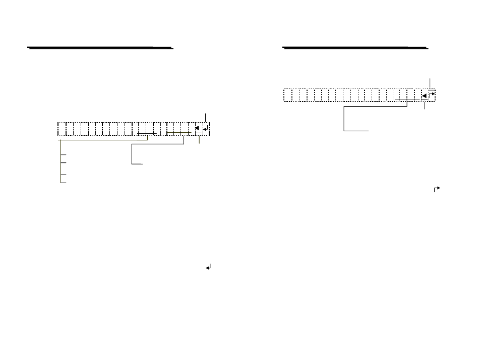
4) Save reference memory setting mode
When the “MENU 4: SAVE” is displayed at the top right of the CRT, the
save reference memory can be selected.
Save completed.
M E N U 4
:
S A V E
C H 1
R
E F 0
Source Waveform:
Setting marker by VARIABLE
CH1: only CH1
CH2: only CH2
REF0: Save to REF0 memory
ADD: only CH1+CH2
∣
SUB: only CH1-CH2
REF0: Save to REF9 memory
The source waveform is automatically switched by vertical mode. When
both CH1 and CH2 are active, pressing the VARIABLE control knob to
select the source waveform between CH1 and CH2.
Turning The VARIABLE control knob clockwise to change the number of
reference memory from REF0 to REF9 and turning the knob
counterclockwise to change the number in the reverse order.
When the source waveform and the number of reference memory are
established, pressing the SAVE pushbutton to write the source waveform
in the memory and indicate the associated readout information of “ ”.
GRS-6052A/6032A OSCILLOSCOPE
USER MANUAL
⎯ ⎯
59
5) RECALL reference
When the “MENU5:RECALL” is displayed at the top right of the CRT,
the recall reference memory can be selected.
Recall Completed
M E N U 4
:
S A V E
C H 1
R
E F 0
Setting marker by VARIABLE
REF0: Recall REF0 memory
∣
REF0: Recall REF9 memory
Turning the VARIABLE control knob clockwise to change the number of
reference memory from REF0 to REF9 while turning the knob
counterclockwise to change the number in the reverse order.
+
Recall the waveform on the CRT by pressing the RECALL pushbutton,
the readout then indicates the associated readout information of “ ”.
When this pushbutton is pressed again, the displayed waveform will be
removed.