GW Instek GRS-6000A Series User Manual
Page 13
GRS-6052A/6032A OSCILLOSCOPE
USER MANUAL
⎯ ⎯
20
The deflection coefficients and additional information regarding the active
channels are displayed in the readout.
VAR
Pressing the VOLTS/DIV control knob to select the VOLTS/DIV function
between attenuator and vernier (variable). The current setting is displayed by
the “>” symbol in the readout.
After switching on the VAR, turn the VOLTS/DIV control knob
counterclockwise to reduce the signal height, and the deflection coefficient
becomes uncalibrated.
(19) CH1 AC/DC
(20) CH2 AC/DC
Pressing the pushbutton briefly to switch over from AC (~ symbol) to DC (=
symbol) input coupling. The setting is displayed in the readout with the
deflection coefficient.
(21) CH1 GND– P×10
(22) CH2 GND – P×10 –Pushbutton of two functions.
GND
Each time when the pushbutton is pressed briefly, the input of the vertical
amplifier is grounded. It is displayed in the readout as an earth (ground)
symbol “ ”.
P×10
Pressing and holding the pushbutton to select the indicated deflection
coefficient of the channel displayed in the readout between 1:1 and 10:1.
The probe factor of 10:1 is displayed in the readout with the probe symbol
“P × 10” in front of channel indication. When proceed cursor voltage
measurement, the probe factor will be automatically included. The symbol
must not be activated unless a 10:1 attenuator probes are used.
GRS-6052A/6032A OSCILLOSCOPE
USER MANUAL
⎯ ⎯
21
(23) CH1-X—Input BNC socket
This BNC socket is the signal input for channel 1. In X-Y mode, signals at
this input are used for the X deflection. The outer (ground) connection is
galvanically connected to the instrument ground and consequently to the
safety earth contact of the line/mains plug.
(24) CH2-Y—Input BNC socket
This BNC socket is the signal input for channel 2. In X-Y mode, signals at
this input are used for the Y deflection. The outer (ground) connection is
galvanically connected to the instrument ground and consequently to the
safety earth contact of the line/mains plug.
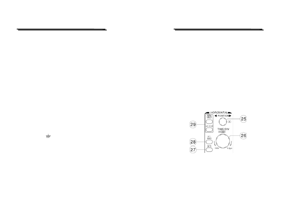
Horizontal controls:
The horizontal controls select the time base operation mode and adjust the
horizontal scale, position and magnification of the signal.