GW Instek GRS-6000A Series User Manual
Page 17
GRS-6052A/6032A OSCILLOSCOPE
USER MANUAL
⎯ ⎯
28
When the setting (voltage) value is out of the changing portion of the
observation waveform, the synchronization sweep stops.
TRG LED
The TRG LED is lit if the triggering conditions are met. Whether the LED
flashes or is lit constantly depends on the frequency of the trigger signal.
(36) HOLD-OFF—Control knob (REAL TIME mode only)
Used when the signal waveform is complex and stable triggering cannot be
attained with the TRIGGER LEVEL(35) knob alone, rotate this control knob
to adjust hold-off time(trigger inhibit period beyond sweep duration). When
control is rotated fully clockwise, the hold-off period is at MINimum
(normal). The hold-off period increases progressively with counterclockwise
rotation.
(37) TRIG EXT—This BNC socket is the external trigger signal input.
Pressing the TRIG. SOURCE (31) pushbutton until the information of “EXT,
slope, coupling” is shown up in the readout switches the input on.
The outer (ground) connection is galvanically connected to the instrument
ground and consequently to the safety earth contact of the line/mains plug.
The maximum input voltages of the input terminal are shown in the section
of 3-6. “Withstanding voltage of Input terminals”. Do not apply voltage
higher than the limit.
GRS-6052A/6032A OSCILLOSCOPE
USER MANUAL
⎯ ⎯
29
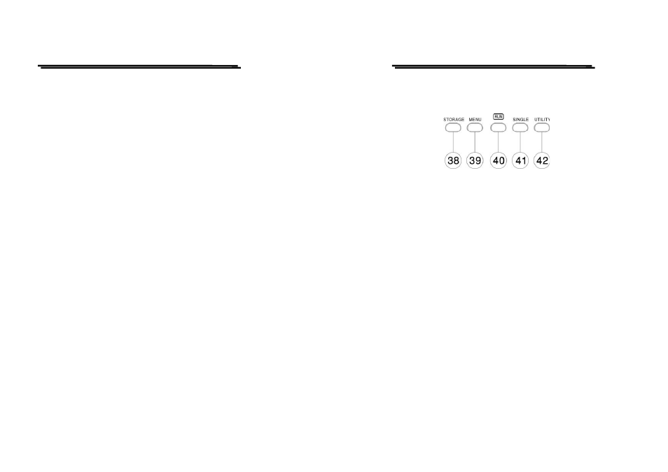
Storage Control
The Storage Control select the digital storage function.
(38) STORAGE/REAL TIME mode
Switch the REAL TIME mode to (digital) STORAGE mode by pressing the
button. In this case, all the switches from (39) to (42) are valid.
When the switch is pressed again in the STORAGE mode, the REAL TIME
mode is established again. In the STORAGE mode, the RUN LED blinks in
synchronism with sampling.
(39) MENU
Press the pushbutton to change the acquisition mode, the smoothing ON or
OFF, the interpolation method and the selection of SAVE/RECALL waveform
memory. Each pressing changes the setting mode and the present setting mode
is displayed at the top right on the CRT. The settings in each mode are
changed by the VARIABLE (9) control knob. Please refer to section 5-7 for
details.
(40) RUN/STOP—Pushbutton and indicator LED
Pressing this pushbutton to stop sampling, resulting in the hold state, and the
RUN LED is off. The current setting is indicated by the readout (“STOP”).
Further pressing the pushbutton to release hold state and start sampling states.