GW Instek GRS-6000A Series User Manual
Page 31
GRS-6052A/6032A OSCILLOSCOPE
USER MANUAL
⎯ ⎯
56
SMPL(0.1s~1μs/div)
In normal sampling mode, the instrument generates a record point by
saving the first sample during each acquisition interval.
PEAK(100s~5μs/div at one channel, 0.5ms~5μs/div at two channels)
The peak detect mode stores the minimum and maximum values (pairs)
for each time bucket. This mode is capable of detecting glitches of 25ns or
more regardless of the sweep rate.
PERSIST(0.1s ~0.2μs/div)
The persistence mode displays the minimum and maximum values
mutually in the normal sampling and initialization by changing the
TIME/DIV control knob. This mode can acquire and display a waveform
record that shows the total variation over entire acquisition.
ENVELOP (0.1s ~5μs/div at one channel, 0.5ms~5μs/div at two
channels)
The Envelope mode activates both peak detect and persistence mode. This
mode monitors signal variations over time. You can measure interference
signals, jitter, amplitude modulated signals and more.
AVERAGE (0.1s ~0.2μs/div)
In the Average mode, pressing the VARIABLE control knob to set the
number of average, turning the knob clockwise to change the number
from 2 to 4-8-16-32-64-128-256 and turning the knob counter-clockwise
to change the number in the reverse order, the average waveform is
displayed after the data of the set sweep number has been acquired.
When the number of average is 16, the data is acquired 16 times (the RUN
LED blinks 16 times). Thus, the non-repetitive signal affected by
asynchronous noise can be picked up. The average operation is
performed by setting the number of average. In the ROLL mode, the
average operation is not performed.
GRS-6052A/6032A OSCILLOSCOPE
USER MANUAL
⎯ ⎯
57
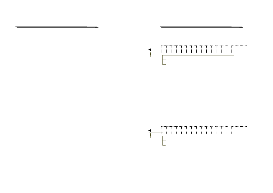
2) Smoothing selection mode
When the “MENU 1: SMOOTH” is displayed at the top right of the CRT,
the smoothing is made on and off.
M
E
N
U
1
:
S
M
O
O
T
H
O
F
F
OFF: No Smoothing
Setting marker by VARIABLE
ON: Smoothing
In case of OFF, the storage waveform is displayed by dots, while changing
to ON, the dots are connected smoothly as result of a smooth waveform
display.
When the sampling frequency is low with respect to the input signal
frequency (when the signal of more than 5 cycles per division is
connected), the amplitude to be display may be small. In this case, set the
smoothing mode to OFF to display the waveform of the similar amplitude
with the input signal. The setting can be done by the VARIABLE control
knob.
3) Interpolation Method Selection mode
When the “MENU 3: INTRPL” is displayed at the top right of the CRT,
THE interpolation Method can be selected.
M
E
N
U
3
:
I
N
T
R
P
L
D
O
T
DOT: No interpolation
Setting marker by VARIABLE
LINEAR: Linear interpolation
The mode selection is made by the VARIABLE control knob. The
interpolation method is how to interpolate the magnified data while
magnifying the display waveform in the horizontal direction (except for
the SAVE/RECALL reference waveform). In the case of DOT, the