GW Instek GRS-6000A Series User Manual
Page 33
GRS-6052A/6032A OSCILLOSCOPE
USER MANUAL
⎯ ⎯
60
5-7.Measurement Application
The oscilloscope has a cursor measurement system for making accurate, direct-
readout voltage, time and frequency measurements. The measurements
described in this section are examples of typical applications using this
measurement system. After becoming familiar with the controls, indicators, and
capabilities of the instrument, you can develop convenient methods to make the
special measurement for your own applications.
Proceed a measurement by using the cursor according to the following steps:
1. Press the [△V—△T, 1/△T—OFF] pushbuttons to turn on the cursor and
measurement readout.
2. Press the pushbutton to select the seven measurement function in the
sequence as below:
△ V —△T —1/△T—OFF
3. Press the [C1—C2 TRK] pushbutton to select C1 cursor, C2 cursor and
tracking cursor.
4. Rotate the VARIABLE control knob to position selected cursor. Press one of
the VARIABLE control knob to select FINE or COARSE cursor move speed.
5. Read the measurement value on the screen. Typical measurement readouts
and applications are shown in Figure 5-16. The measurement values are
automatically controlled by the VOLTS/DIV and TIME/DIV control settings.
GRS-6052A/6032A OSCILLOSCOPE
USER MANUAL
⎯ ⎯
61
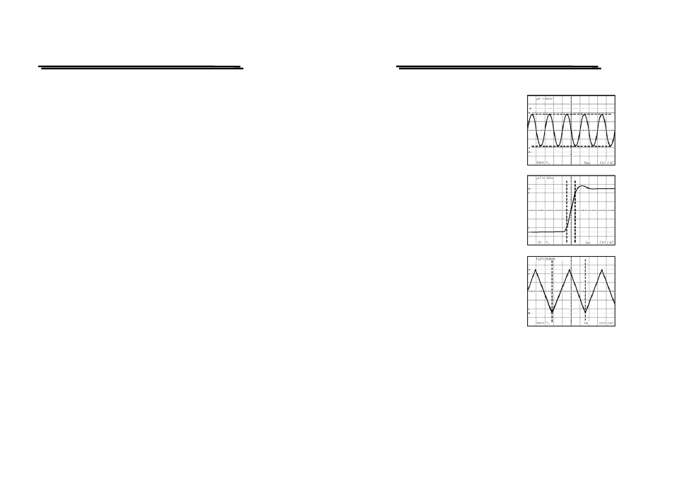
Figure 5-19: Cursor Measurement
(a).Typical △V (Voltage difference) for
AC voltage.
When both CH1 and CH2 are turned on,
the measurement value of CH1(△V1).
(b).Typical △ T(Time difference) cursor
measurement for rise time.
Proceed rise-time or fall-time
measurement requiring some additional
signal scaling by using the graticule
rise-time measurement aids. Number 0%,
10, 90 and 100 are etched near the left
vertical graticule line. Use the following
steps as a guideline to in making rise-
time measurement:
(c).Typical 1/ △ T cursor function for
frequency measurement.
When the two cursors are superimposed
at two edge points of the one period
waveform by the [C1—C2 TRK] and
VARIABLE controls, the measurement
value is displayed in frequency units on the upper side of the screen.
NOTE. When the VOLTS/DIV or the TIME/DIV controls are in uncalibrated
setting, the △ V and △ T measurement values will be displayed with
divisions.
When the vertical mode is set to the ADD mode, and the CH1 and CH2
VOLTS/DIV controls are set to different scales, the △V measurement values
will be displayed with divisions.