GW Instek GRS-6000A Series User Manual
Page 34
GRS-6052A/6032A OSCILLOSCOPE
USER MANUAL
⎯ ⎯
62
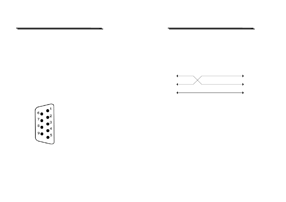
5-8 RS-232 Interface –Remote Control
5-8-1. RS-232 Configuration
The GRS-6052A/6032A contains a DB 9-pin, male RS-232 connector for serial
communication with a computer or terminal. The GRS-6052A/6032A RS-232
interface is configured as an RS-232 “Data Terminal Equipment” so that data is sent
from pin 3 and received on pin 2. For remote controls, the RS-232 interface has to be
connected with a computer or terminal.
Pin Assignments
The pin assignments for RS-232 interface of GRS-6052A/6032A are listed below.
1. No connection
2. Receive Data (RxD)
(input)
3. Transmit Data (TxD) (output)
4. No connection
5. Signal Ground
(GND)
6. No connection
7. No connection
8. No connection
9. No connection
Figure 5-20. Pin assignments of the RS232 connector on the rear panel for DB-9-D
GRS-6052A/6032A OSCILLOSCOPE
USER MANUAL
⎯ ⎯
63
DB9 to DB9 Wiring
The wiring configuration is used for computer with DB9 connectors that configured
as Data Terminal Equipment.
GRS-6052A/6032A
(DB9, DTE)
Computer
(DB9, DTE)
Pin2
Pin3
Pin2
Pin3
Pin5
Pin5
Figure 5-21. DB9 to DB9 wiring
When the GRS-6052A/6032A is set up with a RS232 interface, please check the
following points:
z
Do not connect the output line of one DTE device to the output line of the other.
z
Many devices require a constant high signal on one or more input pins.
z
Ensure that the signal ground of the equipment is connected to the signal
ground of the external device.
z
Ensure that the chassis ground of the equipment is connected to the chassis
ground of the external device.
z
Do not use more than 15m of cable to connect devices to a PC.
z
Ensure the same configurations are used on the device as the one used on PC
terminal.
z
Ensure the connector for the both side of cable and the internal connected line
are met the demand of the instrument.