GW Instek GRS-6000A Series User Manual
Page 15
GRS-6052A/6032A OSCILLOSCOPE
USER MANUAL
⎯ ⎯
24
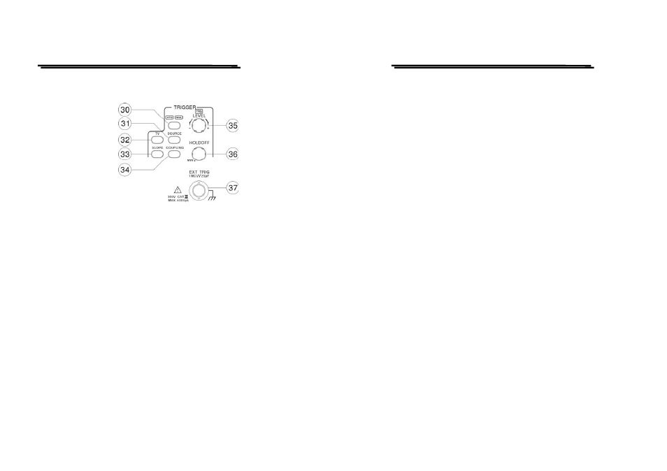
Trigger controls
The trigger controls determine the sweep start timing for both signals.
(30) ATO/NML – Pushbutton and indicator LEDs.
Pressing the pushbutton to select auto or normal trigger mode. The actual
setting is indicated by a LED.
Each time when the pushbutton is pressed the trigger mode changes in the
sequence:
ATO—NML—ATO
ATO (Auto)
Select the automatical mode, the sweep free-runs will display a baseline
trace when there is no trigger signal. The setting of triggering level changed
only when the TRIGGER LEVEL control is adjusted to a new level setting.
NML (Normal)
Select the normal mode, the input signal will trigger the sweep when the
TRIGGER LEVEL control is set within the peak-to-peak limits of an
adequate trigger signal. When the sweep is not triggered, no baseline trace
will be displayed.
Use this mode when effecting synchronization to a very low frequency
signal (25Hz or less).
GRS-6052A/6032A OSCILLOSCOPE
USER MANUAL
⎯ ⎯
25
(31) SOURCE—Pushbutton
Pressing the pushbutton to select the trigger signal source. The actual
setting is indicated by the readout (“SOURCE”, slope, coupling).
Each time when the pushbutton is pressed, the trigger source change in the
sequence:
VERT—CH1—CH2—LINE—EXT—VERT
VERT (Vertical Mode)
For observing two waveforms, the sync signal changes alternately
corresponding to the signals on CH1 and CH2 to trigger the signal.
CH1
The signal applied to the channel 1 input connector is the source of the
trigger signal.
CH2
The signal applied to the channel 2 input connector is the source of the
trigger signal.
LINE
The triggering signal is obtained from a sample of the AC power source
waveform. The trigger source is useful when the displayed waveform
frequency is time related to the AC power source frequency.
EXT
The external signal applied through the EXT input connector is used for the
external triggering source signal.