GW Instek GRS-6000A Series User Manual
Page 25
GRS-6052A/6032A OSCILLOSCOPE
USER MANUAL
⎯ ⎯
44
Comparing Frequency and phase (X-Y Operation)
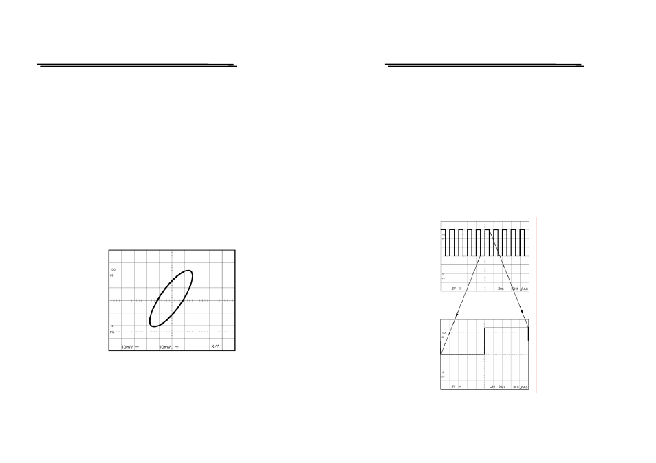
To compare the frequency and phase between two signals by using the X-Y
mode. The X-Y waveform displays different amplitude, frequency, and phase.
The figure 5-7 shows a typical waveform made up of two signals that are of the
same frequency and amplitude, but approximate 45
o
out of phase.
To use the oscilloscope in the X-Y mode, proceed the following steps:
1. Connect the horizontal or X-axis signal to the CH1 input.
2. Connect the vertical or Y-axis signal to the CH2 input.
3. Set the X-Y button to X-Y operation (shown as Fig. 5-7 below).
Use the HORIZONTAL POSITION control to adjust the X-axis.
Note: When high frequency signals are displayed in the X-Y operation,
note the frequency bandwidths and phase difference between X and Y axis.
Refer to “2. SPECIFICATION” section for details.
Figure 5-7 Typical single X-Y display.
GRS-6052A/6032A OSCILLOSCOPE
USER MANUAL
⎯ ⎯
45
Magnifying Waveform Events
Use the MAG pushbutton to view small portions of a waveform as which is too
far back from the starting point to view by using the TIME/DIV control. To use
the MAG button, proceed the following steps:
1. Adjust the TIME/DIV to the fastest sweep that displays the event.
2.Rotate the HORIZONTAL POSITION control to move the event to display
on the center of screen.
3. Press the MAG button.
4.Select MAG ×5, MAG ×10, or MAG ×20 for MAG function.
When above procedures have been done, the displayed waveform will be
expanded 10 times to the right and left from the center of screen as center of
expansion.
Figure 5-8 Magnified Waveform