Led patterns – Brocade ICX 7750 Hardware Installation Guide User Manual
Page 39
Brocade ICX 7750 Hardware Installation Guide
29
53-1003084-01
3
LED patterns
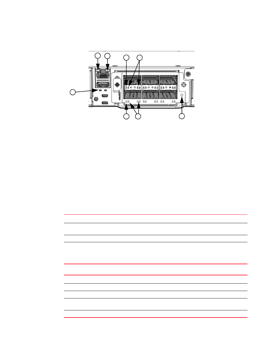
FIGURE 22
Brocade ICX 7750 rear panel LEDs
LED patterns
The following tables describe the Brocade ICX 7750 LED patterns.
1
Management port 10/100 Mbps link/activity
LEDs
5
Upper HA port (left) and lower HA port (right) link
status LEDs
2
Management port 1000 Mbps link/activity LEDs
6
Lower slot 40 GbE mode link/activity LED or 10 GbE
mode lane 1 link/activity LEDs
3
Upper slot 40 GbE mode link/activity LED or
10 GbE mode lane 1 link/activity LEDs
7
Lower slot 10 GbE mode lanes 2, 3, and 4
link/activity LEDs
4
Upper slot 10 GbE mode lanes 2, 3, and 4
link/activity LEDs
8
Expansion module power LED
5
3
4
1
2
8
7
6
TABLE 4
PSU1 and PSU2 LEDs
LED state
Status of hardware
Recommended action
Off (no light)
System is off or there is no power.
Verify the system is on and has
completed booting.
Steady green
PSU is on and functioning properly.
No action required.
Steady amber
PSU is missing power or in a faulty state.
Verify that the PSU power cord is
connected to a functioning power
source.
Replace power supply.
TABLE 5
DIAG LED
LED state
Status of hardware
Recommended action
Off (no light)
Diagnostic is off.
No action required.
Blinking green
System self-diagnostic test is in progress.
No action required.
Steady green
System self-diagnostic test is successfully
completed.
No action required.
Steady amber
System self-diagnostic test has detected a fault. Contact support.