Brocade ICX 7750 Hardware Installation Guide User Manual
Page 36
26
Brocade ICX 7750 Hardware Installation Guide
53-1003084-01
3
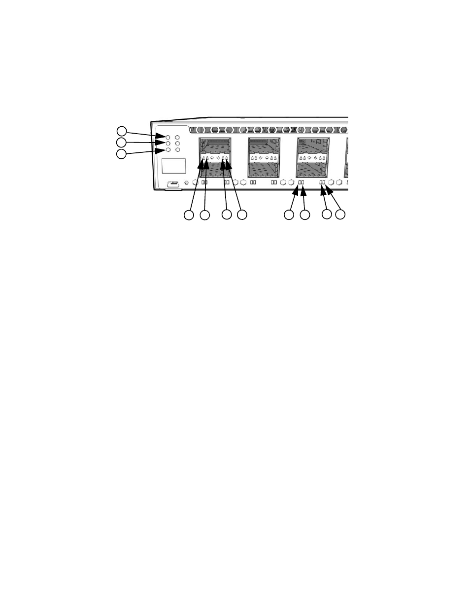
Brocade ICX 7750 front panel LEDs
shows the LEDs on the Brocade ICX 7750-26Q front panel.
FIGURE 19
Brocade ICX 7750-26Q front panel LEDs
The Brocade ICX 7750-48C has the following LEDs on the front panel:
•
Two power supply unit (PSU) bicolor status LEDs (green and amber) labeled PSU1 and PSU2.
•
One DIAG LED bicolor status LED (green and amber).
•
One MS LED bicolor status LED (green and amber).
•
One HA LED bicolor status LED (green and amber).
•
One RDNT LED bicolor status LED (green and amber).
•
48 1/10 GbE bicolor status LEDs (green for 10 GbE and amber for 1 GbE) which indicate 1 GbE
or 10 GbE mode of operation.
•
Four bicolor status LEDs (green and amber) for each of the six QSFP+ ports that indicate the
status of the ports in 40 GbE mode and 4x10 GbE breakout mode.
1
PSU1 and PSU2 status LEDs
(PSU1 corresponds to the right power supply slot
on the back panel and PSU2 corresponds to the
left power supply slot, as viewed from the rear)
7
Upper slot 10 GbE mode lane 4 link/activity LED
2
MS and DIAG status LEDs
8
Lower slot 40 GbE mode link/activity LED or 10 GbE
mode lane 1 link/activity LED
3
HA and RDNT status LEDs
9
Lower slot 10 GbE mode lane 2 link/activity LED
4
Upper slot 40 GbE mode link/activity LED or
10 GbE mode lane 1 link/activity LED
10 Lower slot 10 GbE mode lane 3 link/activity LED
5
Upper slot 10 GbE mode lane 2 link/activity LED
11 Lower slot 10 GbE mode lane 4 link/activity LED
6
Upper slot 10 GbE mode lane 3 link/activityy LED
2
4
5
6
7
3
1
8
9
10 11