Profibus dp rui/gtw led indicators – Watlow EZ-ZONE RUI/Gateway User Manual
Page 41
Watlow EZ-ZONE
®
RUI/Gateway
•
38
•
Chapter 5 Networking with a Gateway
Slot Offset = 61
Index = 0
Profibus DP RUI/GTW LED Indicators
Viewing the unit from the front and then looking on
top of the RUI/GTW two bi-color LEDs can be seen
where only the front one is used. Definition follows:
Closest to the Front
Indicator LED
Description
Red
Profibus network not detected
Red
Flashing
Indicates that the Profibus card is
waiting for data exchange.
Green
Data exchange mode
To learn more about Profibus DP point your browser
to:
As with all of the other available protocols prior
to establishing communications between Master and
the slave the gateway instance must first be enabled
[du;en]
. Once enabled, the user must define the Slot
Offsets for each enabled EZ-ZONE controller.
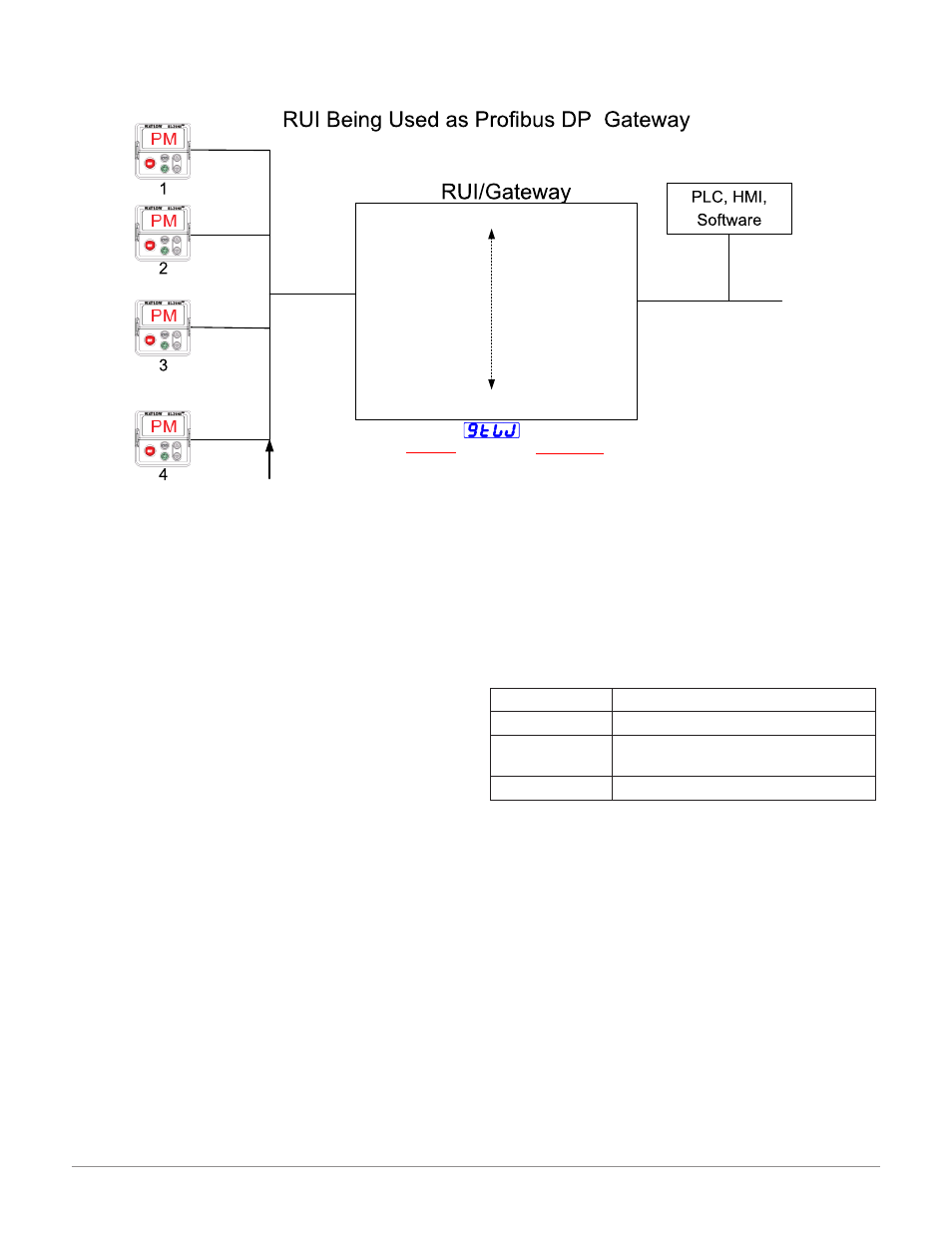
Use the graphic below (RUI being used as a Profi-
bus DP Gateway) in reference to the descriptions that
follow below.
[`s;of]
Slot Offsets are used exclusively with acyclic
(DP-V1) communications and define the in-
dividual EZ-ZONE controller on the network
as well as the instance of the parameter to
be read or written to. The offset defaults are
as shown in the graphic in increments of 20,
however, they can be changed based on user
needs.
As an example, when programming the Master device
ensure that the Slot Offset and the Profibus Index
(found in each product user manual in the various
menus) are defined. To read the first instance of the
Process Value in PM2 use the following information
when programming the Master:
Slot Offset = 20
Index = 0 (See the EZ-ZONE PM Users Manual,
Operations Page under the Analog Input
Menu)
Note that PM2 and instance 1 is identified in the
Slot Offset where the parameter, in this case, Process
Value 1 is identified via the Profibus Index. If it were
instance 2 same parameter that was needed the Slot
Offset would change to 21.
Likewise, to read the Process Value instance 2 of PM4
the following information would need to be entered
when programming the Master:
[gtW]
1 = PM1
[gtW]
4 = PM4
Address Lock
[a;loc]
= [yes] or [no]
[Com]
Instance 2
Units
[`C_f]
= [``f] or
[``C]
Profibus DP
Watlow Standard Bus
(Daisy chain EIA-485)
EZ-ZONE
®
Controllers
1 - 16 maximum
Profibus Slot
Offset
0
Profibus Address
[p;add]
= 0 - 126
[Com]
Instance 1
Standard Bus Address
[Ad;S]
= 1-8
Start Node to Scan
[St;2n]
= 1-24
End Zone to Scan
[nU;2n]
= 1-24
RUI/Gateway
Setup Prompts
Profibus DP
[gtW]
= 1 – 16
(Gateway Instance)
[Du;En]
= Yes or No
(Enable gateway instance)
Gateway
[Du;st]
= [On] or [off]
(Device Status)
[`s;of]
= 0 - 254
(Profibus Slot Offset)
Profibus Slot
Offset
20
Profibus Slot
Offset
40
Profibus Slot
Offset
60