Watlow EZ-ZONE RUI/Gateway User Manual
Page 20
Watlow EZ-ZONE
®
RUI/Gateway
•
17
•
Chapter 3 Keys and Displays
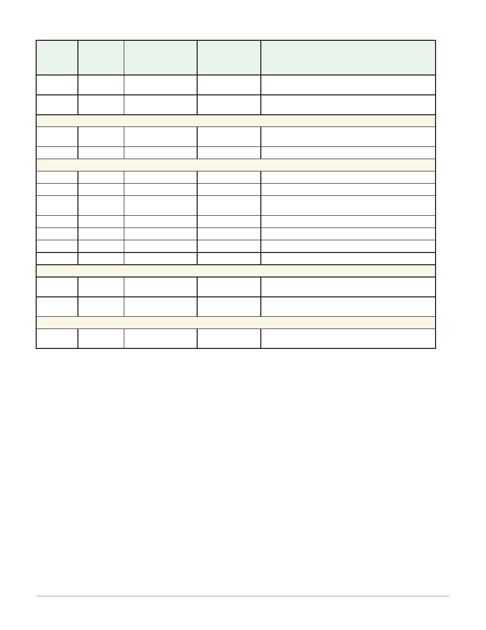
EZ-ZONE ST Home Page
Custom
Menu
Number
Home
Page
Display
(defaults)
Parameter
Name
Custom Menu
Display
(defaults)
Parameter Page and Menu
1 Upper
Display
(value
only)
Active Process
Value
[AC;Pu]
Operations Page, Analog Input Menu
2 Lower
Display
(value
only)
*Active Set Point
[AC;SP]
Operations Page, Monitor Menu
IF 4
th
digit of PN is equal to: ST _ [L] - _ _ _ _ - _ _ _ _ (Integrated Limit included)
3
(value
only)
Process Value
Analog Input 2
[`pro]
Operations Page, Analog Input Menu
4
[l;st]
Limit State
[`l;st]
Operations Page, Limit Menu
IF 4
th
digit of PN is equal to: ST _ [A] - _ _ _ _ - _ _ _ _
3
None
- - - -
- - - -
- - - -
4
None
- - - -
- - - -
- - - -
5
[C;m1]
User Control
Mode
[`C;m]
Operations Page, Monitor Menu
6
[h;Pr1]
Heat Power
[`h;Pr]
Operations Page, Monitor Menu
7
[C;Pr1]
Cool Power
[`C;Pr]
Operations Page, Monitor Menu
8
[AUt1]
Autotune
[`AUt]
Operations Page, Loop Menu
9
[id;s1]
Idle Set Point
[idLE]
Operations Page, Loop Menu
IF 12
th
digit of PN is equal to: ST _ _ - _ _ _ _ - _ [P] _ _ (Profile Ramp and Soak included)
10
[P;ST1]
Profile Start
[P;Str]
Home Page only (See ST User Manual, Pro-
file Page Chapter.)
11
[P;AC1]
Profile Action Re-
quest
[P;ACr]
Home Page only (See ST User Manual, Pro-
file Page Chapter.)
IF 12
th
digit of PN is equal to: ST _ _ - _ _ _ _ - _ [A, S] _ _
10 to 20 (skipped)
None
[nonE]
(Add parameters to the Home Page in the
Custom Menu, Factory Page.)
*
If Control Mode is set to Auto, the process value is in the upper display and the Closed Loop Set Point
(read-write) is in the lower display.
If a profile is running, the process value is in the upper display and the Target Set Point (read only) is in
the lower display.
If Control Mode is set to Manual, the process value is in the upper display and the output power level (read-
write) is in the lower display.
If Control Mode is set to Off, the process value is in the upper display and [`oFF] (read only) is in the lower
display.
If a sensor failure has occurred, [----] is in the upper display and the output power level (read-write) is in
the lower display.