Ethernet/ip™ and modbus tcp communications, Devicenet™ communications, Profibus dp communications – Watlow EZ-ZONE RUI/Gateway User Manual
Page 10
Ó
Warning:
Use National Electric
(NEC) or other country-
specific standard wiring
and safety practices when
wiring and connecting
this controller to a power
source and to electrical
sensors or peripheral de-
vices. Failure to do so may
result in damage to equip-
ment and property, and/or
injury or loss of life.
Watlow EZ-ZONE
®
RUI/Gateway
•
7
•
Chapter 2 Install and Wire
EtherNet/IP™ and Modbus TCP Communications
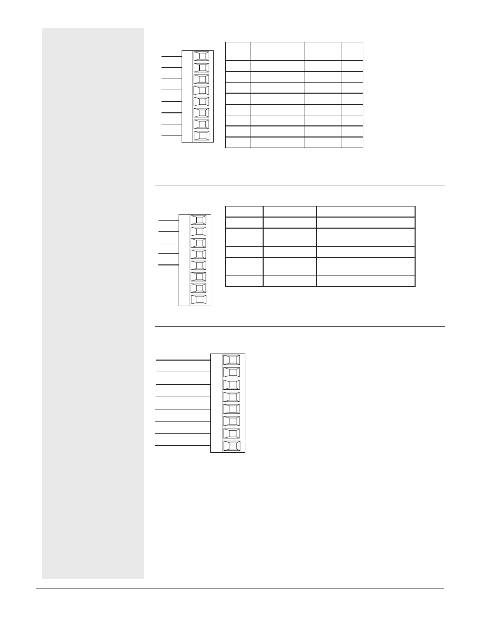
Ethernet IP
receive -
unused
E8
E7
E6
E5
E4
E3
E2
E1
Slot B
unused
unused
unused
receive +
transmit -
transmit +
RJ-45
pin
T568B wire
color
Signal
Slot
B
8
brown
unused
E8
7
brown & white
unused
E7
6
green
receive -
E6
5
white & blue
unused
E5
4
blue
unused
E4
3
white & green
receive +
E3
2
orange
transmit -
E2
1
white & orange
transmit + E1
• Do not route network
wires with power wires.
• Connect one Ethernet
cable per device to a
10/100 mbps Ethernet
switch. Both Modbus
®
TCP and EtherNet/IP™
are available on the
network.
Note:
When changing the fixed IP address on the RUI cycle module power for new address to take ef-
fect.
DeviceNet™ Communications
Devicenet
CAN_L
V-
V+
CH
SH
CL
V-
T2
S2
R2
Slot B
V+
CAN_H
shield
Terminal
Signal
Function
V+
V+
DeviceNet™ power
CH
CAN_H
positive side of DeviceNet™
bus
SH
shield
shield interconnect
CL
CAN_L
negative side of DeviceNet™
bus
V-
V-
DeviceNet™ power return
Profibus DP Communications
485 T-/R-
+5Vdc Voltage Potential
VP
B
A
DG
trB
B
A
trA
Slot B
485 T+/R+
Digital ground
Termination resistor B
485 T+/R+
485 T-/R-
Termination resistor A
• Wire T-/R- to the A
terminal of the EIA-
485 port.
• Wire T+/R+ to the B
terminal of the EIA-
485 port.
• Wire Digital Ground
to the common ter-
minal of the EIA-485
port.
• Do not route network
wires with power
wires. Connect net-
work wires in daisy-
chain fashion when
connecting multiple
devices in a network.
• A termination resistor
should be used if this
controller is the last
one on the network.
• If using a 150 Ω cable
Watlow provides inter-
nal termination. Place
a jumper across pins
trB and B and trA and
A.
• If external termina-
tion is to be used with
a 150 Ω cable place a
390 Ω resistor across
pins VP and B, a 220
Ω resistor across pins
B and A, and lastly,
place a 390 Ω resistor
across pins DG and A.
• Do not connect more
than 32 EZ-ZONE
devices on any given
segment.
• Maximum EIA-485
network length: 1,200
meters (4,000 feet)
• 1/8th unit load on
EIA-485 bus.