Using modbus tcp, Ethernet rui/gtw led indicators – Watlow EZ-ZONE RUI/Gateway User Manual
Page 39
Watlow EZ-ZONE
®
RUI/Gateway
•
36
•
Chapter 5 Networking with a Gateway
outputs from the Master and is used exclu-
sively when communicating implicitly. For
any given RUI gateway instance (EZ-ZONE
controller), the input assembly size will never
be greater than 20, 32-bit members. The user
entry ranges from 0 to 20.
Note:
The maximum number of implicit input/output
members using EtherNet/IP cannot exceed 100. A
network could have up to 5 EZ-ZONE controllers
with 20 members each maximum or the 100 mem-
bers can be divided any way the user would like
as long as 20 I/O members per controller are not
exceeded.
Using the graphic on the following page as an ex-
ample, if:
[Gtw]
instance 1 has [ai;nb] and [ao;nb] set to 5
[Gtw]
instance 2 has [ai;nb] and [ao;nb] set to 5
[Gtw]
instance 3 has [ai;nb] and [ao;nb] set to 5
[Gtw]
instance 4 has [ai;nb] and [ao;nb] set to 5
Each of the four EZ-ZONE family controllers will
contain the first 5 members of the assembly and this
information would then be passed implicitly to the
Master on the EtherNet/IP network.
Using Modbus TCP
Communications To/From a Master:
When Modbus TCP is enabled there are Modbus re-
lated prompts (violet as shown in graphic) that need
to be addressed. They are:
1. Modbus TCP Enable [mb;e], turns Modbus on or
off.
2. Modbus TCP Word Order [m;hl], which allows
the user to swap the high and low order 16 bit
values of a 32-bit member.
3. Modbus TCP Offset [m;of], which defines each of
the available Modbus registers for each gateway
instance.
As an example, when using Modbus TCP notice that
the Modbus offset now applies. For the purpose of
this discussion assume the offsets are as shown in
the graphic on the following page and the Master
wants to read the first instance of Closed Loop Set
Point from both Standard Bus address 1 and 4. Open
up the appropriate PM users manual and go to the
Operations Page, Loop Menu to find the Closed Loop
Set Point.
Note:
If using a legacy EZ-ZONE ST controller with a
firmware version less the 3.0, consider using the
Modbus addresses listed in the ST user manual
in the column entitled "RUI/GTW Modbus". If the
firmware in the ST is 3.0 or higher new features
were added and made accessible through the Map2
registers. If interested in using the new features
today or perhaps in the future configure the ST for
Map 2 Modbus registers.
When found, notice that the relative Modbus regis-
ter is 2160 (Map 1) or 2640 (Map 2). To read the set
point from address 1 the appropriate absolute Mod-
bus address would be:
2160 + 400001 + Modbus offset (0) = 402161.
To read the Closed Loop Set Point from Standard Bus
address 4 the absolute address would be:
2160 + 400001 + Modbus offset (15000) = 417161.
Note:
To minimize traffic and enable better throughput
on Standard Bus, set the End Zone prompt [nU;2n]
in the RUI to the maximum number of EZ-ZONE
controllers on the network to be scanned.
Note:
The RUI/GTW allows for a maximum entry of 9999
due to limitations of the 7 segment display. To en-
ter a Modbus offset > 9999 EZ-ZONE Configurator
must be used..
Note:
In the above graphic there are several prompts
omitted for the sake of saving some space. When
the Ethernet addressing mode is set to Fixed the
user will find several more prompts that will follow
the prompt shown for "Ethernet Addressing Mode"
related to specifying the actual IP [ip;f1] - [ip;f4],
subnet [ip;s1] - [ip;s4] and the gateway [ip;g1]
- [ip;g4] (external gateway) addresses. If set to
receive an IP address from a host [dhCp]computer,
the prompts shown above are accurate.
Note:
When changing the RUI/GTW IP address, power
must be cycled for the new address to take effect.
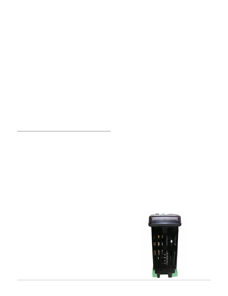
Ethernet RUI/GTW LED Indicators
Viewing the unit from the front and then looking on
top of the RUI/GTW four LEDs can be seen aligned
vertically front to back. The LEDs are identified ac-
cordingly: closest to the front reflects the Network
(Net) status, Module (Mod) status is next, Activity
status follows and lastly, the LED closest to the rear
of the RUI/GTW reflects the Link status.