Chapter 5: using an rui/gateway, Conceptual view of the rui/gtw, Using rui lockout and password security – Watlow EZ-ZONE RUI/Gateway User Manual
Page 32: Using lockout method 1 (read and set lock)
Watlow EZ-ZONE
®
RUI/Gateway
•
29
•
Chapter 5 Networking with a Gateway
Chapter 5: Using an RUI/Gateway
5
Conceptual View of the RUI/GTW
As shown in the following network screen shots the
gateway allows for connectivity between dissimilar
networks. Within the Watlow controllers there are
many parameters (members), of which, some can be
read and some read and or written to. As an example,
the Process Value can be read only, where the Closed
Loop Set Point can be read and or written to. In order
for these parameters to be available on the field bus
side of the gateway some basic setup is required in
the RUI/GTW. Communications instance 1 will al-
ways represent the Standard Bus side of the network
where communications instance 2 represents the field
bus side. On each side of the RUI/GTW there are ad-
dresses (unique to each network) that need to be set
up; there are also some network specific settings as
well. As an example, when using DeviceNet™ as the
field bus of choice, the network baud rate and node
address must be specified. When using Ethernet the
user can enable EtherNet/IP™ and or Modbus TCP.
On the Standard Bus side, the user will determine
the total number of EZ-ZONE
®
controllers (slaves) to
scan (starting and end zones). Once the RUI/GTW is
configured, all accessible parameters for each of the
EZ-ZONE controllers on the Standard Bus network
will be available on the field bus side of the Gateway.
Note:
Excessive writes through the gateway to other EZ-
ZONE family controllers may cause premature EE-
PROM failure. For more detail, open the associated
controller User Guide to find the Non-Volatile Save
prompt [`nU;S]. Turn to the Setup Page and then
under the Com Menu and set this prompt to Yes
(enable writes) or No (disable writes). To learn more
turn to the section entitled "
".
Using RUI Lockout and Password Security
If unintentional changes to parameter settings might
raise safety concerns or lead to downtime, you can use
the lockout feature to make them more secure. There
are two methods of lockout that can be deployed
through the RUI, both of which are accessible from
the RUI Page. Method 1 is discussed below.
Method 1- Change the value of the Read Lock [rloc]
(1 to 5) and Set Lock [sloc] (0 to 5)
prompts where the higher the value or set-
ting for each translates to a higher secu-
rity clearance (greater access).
Note:
When using Method 1 Lockout all settings can be
modified by anyone who knows how to find their
way to the [SLoC] and [rloC] parameters.
Note:
These lockout settings apply to the RUI only. When
utilizing Method 1 described above, the RUI set-
tings may serve as an override to the local PM set-
tings when it too is using Method 1. As an example,
if a PM control has Read Lock set to 1 and the RUI
has the same prompt set to 5, the RUI will have full
visibility to all PM menus when connected to it.
An example of Method 1 lockout usage could be that
it is determined that an operator should have read
access to all menus while allowing write access to the
Home Page only.
1. Press and hold the Advance and Infinity keys for
approximately 6 seconds to enter the RUI Page
2. Navigate to the [`LoC] Menu using the Up or
Down arrow keys
3. Using the green Advance key navigate to the
Read Lockout Security [rLoC] and change it to 5
4. Push the green Advance key and navigate to the
and Set Lockout Security [SLoC] changing it to 1
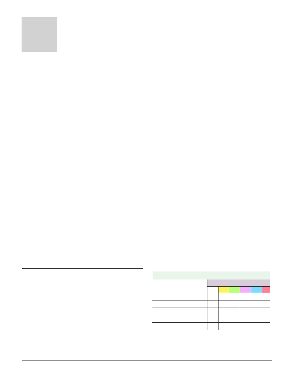
Using Lockout Method 1 (Read and Set Lock)
There are two Pages within an RUI (Home and RUI
Page) that are always visible regardless of Read and
Set Lock settings. However, the menus that are vis-
ible and which ones can be written to are dependent
on these settings. Looking at the table below, "Y"
equates to yes (can write/read) where "N" equates to
no (cannot write/read). The colored cells simply differ-
entiate one level from the next. As stated previously,
the Set Lockout has 6 levels (0 to 5) of security where
the Read Lockout has 5 (1 to 5). Therefore, level "0"
applies to Set Lockout only.
RUI Page Menus
[rloC]
and [sloC]
Menus
Security Level
0
1
2
3
4
5
Communications Menu
N
N
N
N
N
Y
Global Menu
N
N
N
N
N
Y
Gateway Menu
N
N
N
N
N
Y
Lock Menu
N* Y* Y* Y* Y* Y
Diagnostic Menu**
N
Y
Y
Y
Y
Y
* Visible, with limited write capabilities. Read and
Set Lock can always be written to.
** Always visible and never writable