Using ethernet/ip, Ethernet communications – Watlow EZ-ZONE RUI/Gateway User Manual
Page 38
Watlow EZ-ZONE
®
RUI/Gateway
•
35
•
Chapter 5 Networking with a Gateway
Module Status (MS) cont.
Indicator LED
Description
Flashing Red
Major Recoverable Fault.
Red
Major Unrecoverable Fault.
Green
The device is operating nor-
mally.
To learn more about CIP and DeviceNet point your
browser to:
Ethernet Communications
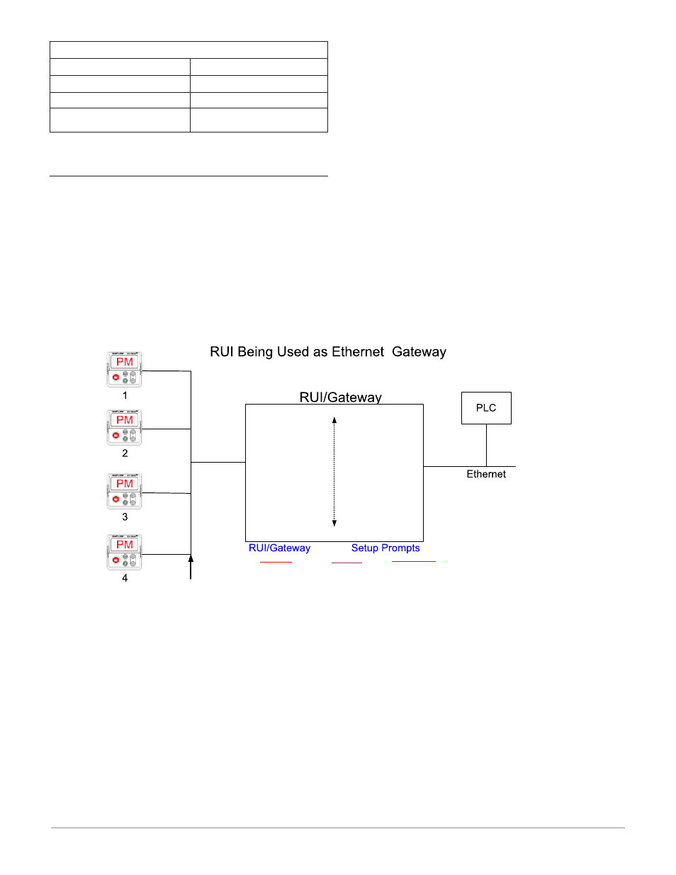
Using EtherNet/IP™
Communications To/From Third Party Device:
When using the EtherNet/IP protocol, there are two
methods used in communicating, implicitly and ex-
plicitly. Once the gateway instance is enabled there
are two prompts that relate directly to these forms of
communication.
Use the graphic below in reference to the descrip-
tions that follow below.
[`ost]
CIP Offset, used exclusively with explicit
messaging where it defines a specific gateway
instance (EZ_ZONE PM or RM controller) to
receive a message originating from the net-
work Master. The CIP offset is unique to each
gateway instance and is added to the pub-
lished instance of any given parameter.
As an example, when programming an explicit mes-
sage ensure that the class, instance and attribute is
defined. To read the first instance of the Process Vari-
able in PM2 use the following information in the mes-
sage instruction:
Class = 104 or (0x68)
Instance = 1
Attribute = 1
Note that the instance is identified as instance 1 be-
cause there is no offset to add. RUI prompt entry for
gateway instance 1 follows:
[`oSt]
= 0
RUI prompt entry for gateway instance 2 (PM2) fol-
lows:
[`oSt]
= 4
RUI prompt entry for gateway instance 3 follows:
`oSt]
= 8
RUI prompt entry for gateway instance 4 follows:
[`oSt]
= 12
To read the process value instance 2 of PM4 add
the offset to the instance. The following information
would need to be entered in the message instruction:
Class = 104 or (0x68)
Instance = 14 or (0x0E)
Attribute = 1
[ao;nb]
From the gateway perspective, this assembly
represents data that comes from Standard
Bus controllers (EZ-ZONE PM or RM) and
is sent out on the network. As seen from the
network, this is the CIP Implicit Output As-
sembly representing inputs to the Master
and is used exclusively when communicat-
ing implicitly. For any given RUI gateway
instance (EZ-ZONE controller), the output
assembly size will never be greater than 20,
32-bit members. The user entry ranges from
0 to 20.
[ai;nb]
From the gateway perspective, this assembly
represents data that comes from the network
Master and is sent to one or more gateway
instance (EZ-ZONE PM or RM) on Standard
Bus. As seen from the network, this is the
CIP Implicit Input Assembly representing
[gtW]
[gtW]
1 = PM1
[gtW]
4 = PM4
Watlow Standard Bus
(Daisy chain EIA-485)
EZ-ZONE
®
Controllers
1 - 16 maximum
CIP Offset
13-16
CIP Offset
9-12
CIP Offset
5-8
CIP Offset
1-4
[Com]
Instance 1
Standard Bus Address
[Ad;S]
= 1-8
Start Node to Scan
[St;2n]
= 1-24
End Zone to Scan
[nU;2n]
= 1-24
Modbus Word Order
[m;hl]
= [lohi] or [hilo]
[Com]
Instance 2
Ethernet Addressing Mode
[ip;m]
= [f;add] or [dhcp]
Modbus Enable
[mb;e]
= [yes] or [no]
EtherNet/IP Enable
[eip;e]
= [yes] or [no]
Gateway
[gtW]
= 1 – 16
(Gateway Instance)
[Du;En]
= Yes or No
(Enable gateway instance)
[Du;st]
= [On] or [off]
(Device Status)
EtherNet/IP
TM
[Ao;nb]
CIP Output Assembly Size
[Ai;nb]
CIP Input Assembly Size
[oSt]
= 0 - 255
(CIP Offset)
Modbus
[m;of]
= 0 - 9999
(Modbus Offset)
Modbus Offset
10000
Modbus Offset
0
Modbus Offset
5000
Modbus Offset
15000
Units
[`C_f]
= [``f] or [``C]