Devicenet rui/gtw led indicators – Watlow EZ-ZONE RUI/Gateway User Manual
Page 37
Watlow EZ-ZONE
®
RUI/Gateway
•
34
•
Chapter 5 Networking with a Gateway
ing information in the message instruction:
Class = 104 or (0x68)
Instance = 1
Attribute = 1
Note that the instance is identified as instance 1 be-
cause there is no offset to add. RUI prompt entry for
gateway instance 1 follows:
[`oSt]
= 0
RUI prompt entry for gateway instance 2 (PM2) fol-
lows:
[`oSt]
= 4
RUI prompt entry for gateway instance 3 follows:
`oSt]
= 8
RUI prompt entry for gateway instance 4 follows:
[`oSt]
= 12
To read the process value instance 2 of PM4 add
the offset to the instance. The following information
would need to be entered in the message instruction:
Class = 104 or (0x68)
Instance = 14 or (0x0E)
Attribute = 1
[ao;nb]
From the gateway perspective, this assembly
represents data that comes from Standard
Bus controllers (EZ-ZONE PM or RM) and
is sent out on the network. As seen from the
network, this is the CIP Implicit Output As-
sembly representing inputs to the Master
and is used exclusively when communicat-
ing implicitly. For any given RUI gateway
instance (EZ-ZONE controller), the output
assembly size will never be greater than 20,
32-bit members. The user entry ranges from
0 to 20.
[ai;nb]
From the gateway perspective, this assembly
represents data that comes from the network
Master and is sent to one or more gateway
instance (EZ-ZONE PM or RM) on Standard
Bus. As seen from the network, this is the
CIP Implicit Input Assembly representing
outputs from the Master and is used exclu-
sively when communicating implicitly. For
any given RUI gateway instance (EZ-ZONE
controller), the input assembly size will never
be greater than 20, 32-bit members. The user
entry ranges from 0 to 20.
Note:
The maximum number of implicit input/output
members using DeviceNet cannot exceed 200. A net-
work could have up to 10 EZ-ZONE controllers with
20 members each maximum or the 200 members
can be divided any way the user would like as long
as 20 I/O members per controller are not exceeded.
Using the graphic below as an example, if [Gtw]
instance 1 - 4 has [ao;nb] and [ai;nb] set to 5, each
of the four EZ-ZONE family controllers will contain
the first 5 members of the assembly and this informa-
tion would then be passed implicitly to the Master on
the DeviceNet™ network. The EDS (Electronic Data
Sheet) can be found on the CD shipped with the prod-
uct "Controller Support Tools".
Note:
To minimize traffic and enable better throughput
on Standard Bus, set the End Zone prompt [nU;2n]
in the RUI to the maximum number of EZ-ZONE
controllers on the network to be scanned.
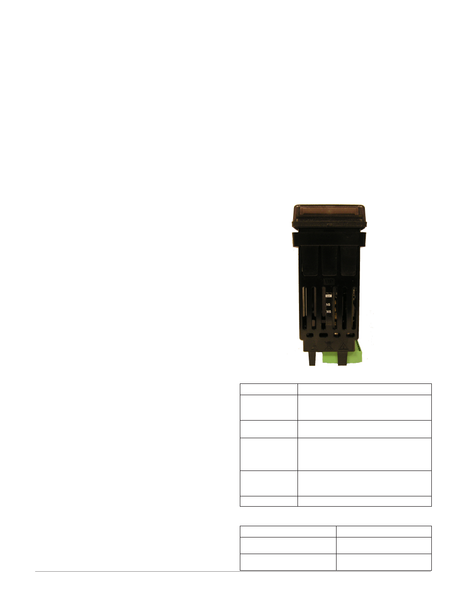
DeviceNet RUI/GTW LED Indicators
Viewing the unit from the front and then looking on
top of the RUI/GTW two LEDs can be seen aligned
vertically front to back. The LED closest to the front
is identified as the network (Net) LED where the one
next to it would be identified as the module (Mod)
LED.
Network Status (NS)
Indicator LED Description
Off
The device is not online and has not com-
pleted the duplicate MAC ID test yet. The
device may not be powered.
Green
The device is online and has connections in
the established state (allcated to a Master).
Red
Failed communication device. The device
has detected an error that has rendered it
incapable of communicating on the network
(duplicate MAC ID or Bus-off).
Flashing Green
The device is online, but no connection has
been allocated or an explicit connection has
timed out.
Flashing Red
A poll connection has timed out.
Module Status (MS)
Indicator LED
Description
Off
No power is applied to the
device.
Flashing Green-Red
The device is performing a
self-test.